Control of an image capturing device

Active Publication Date: 2013-12-05
AXIS
View PDF0 Cites 6 Cited by
  • Summary
  • Abstract
  • Description
  • Claims
  • Application Information

AI Technical Summary

Benefits of technology

[0006]In view of the above, it is thus an object of the present invention to overcome or at least mitigate the above-mentioned drawbacks and t

Problems solved by technology

Due to latencies in the network, in the camera or in the client device, there will be a time delay from the time when the camera control is performed up to the time when a camera-controlled image arrives.
Since the images shown to the operator are lagging, it becomes difficult to control

Method used


Image

  • Control of an image capturing device
  • Control of an image capturing device
  • Control of an image capturing device

Examples


Example

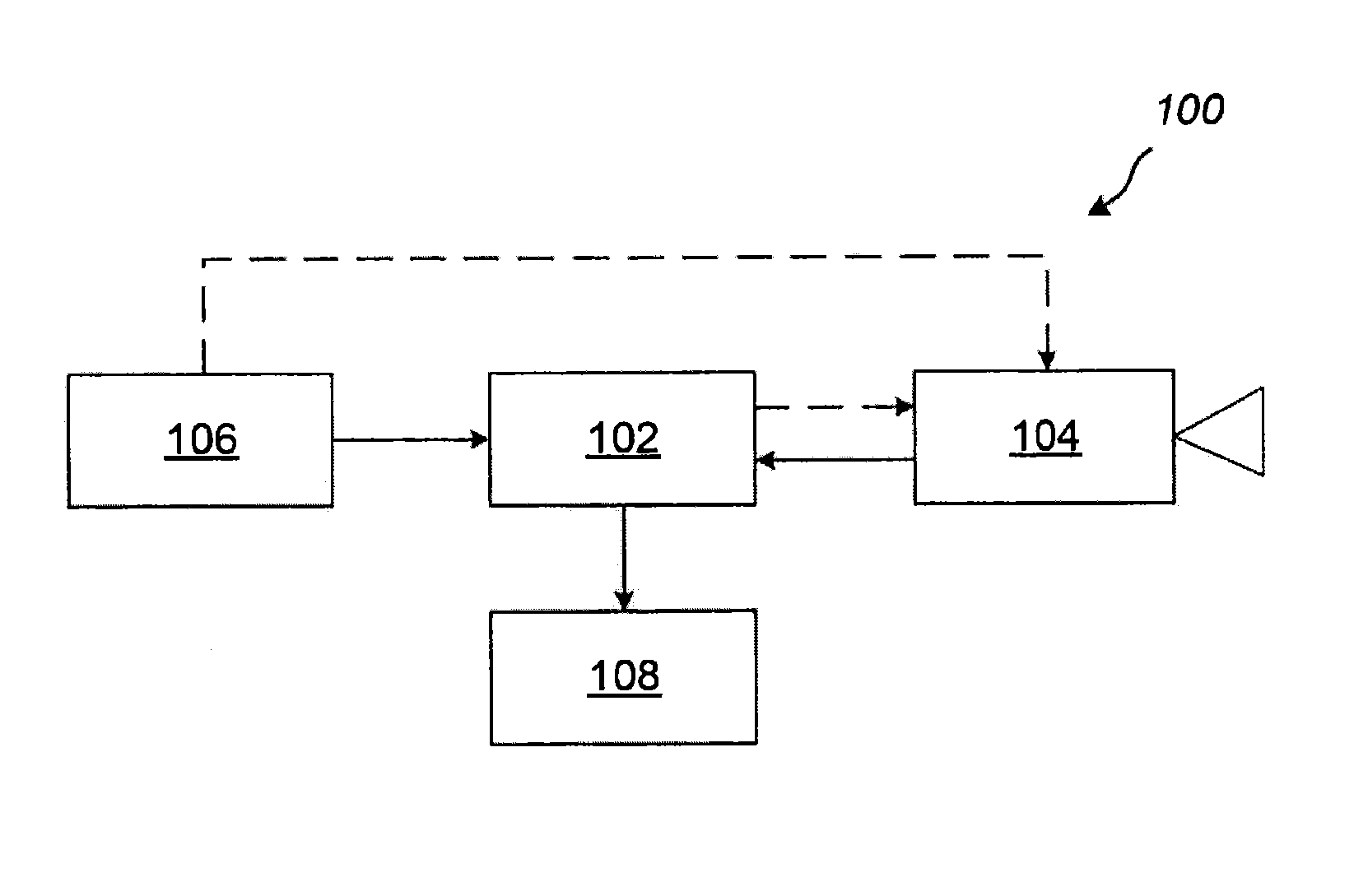
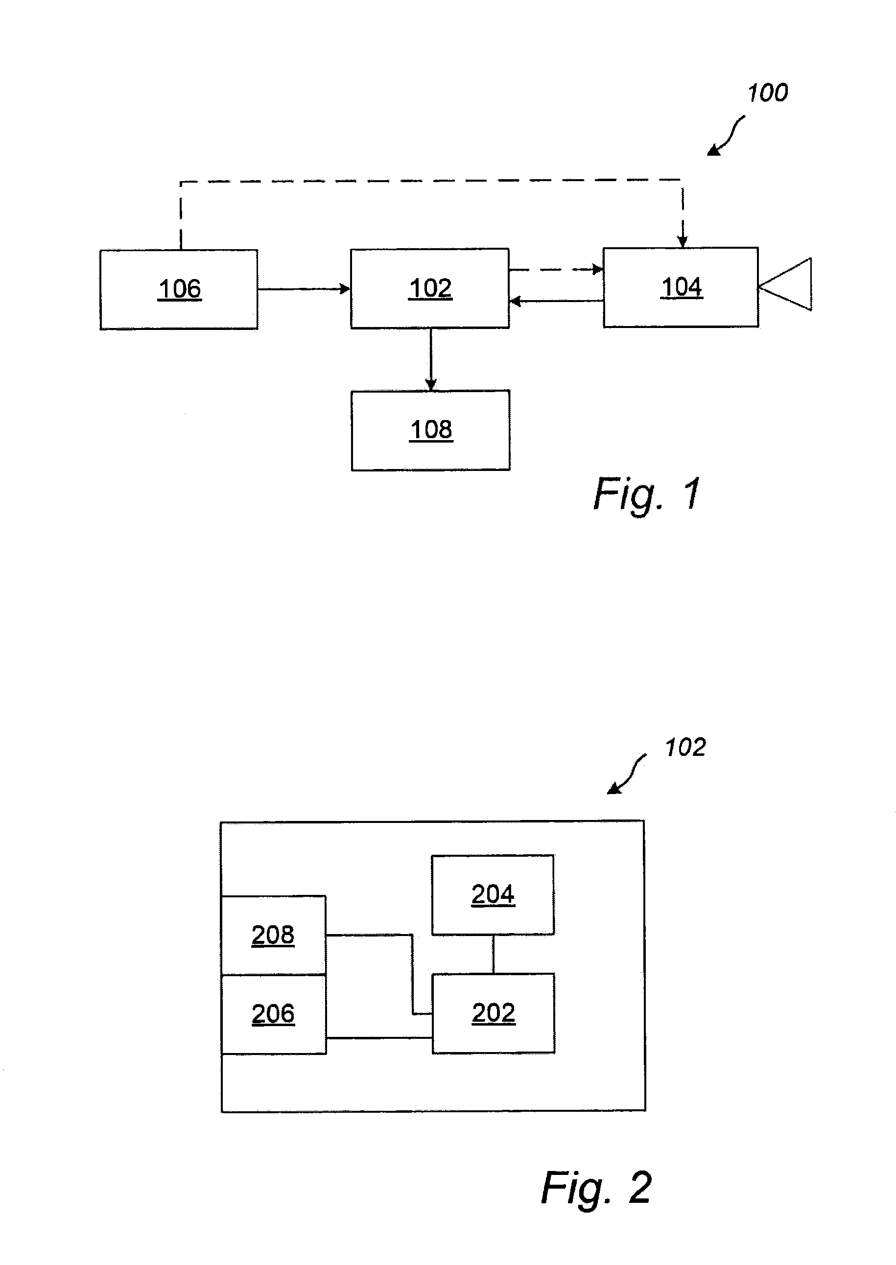
[0045]FIG. 1 illustrates an embodiment of a system 100 for displaying images to an operator of an image capturing device 104. The system 100 will be described in an operating state. The system comprises a processing device 102 which is operatively connected to an image capturing device 104, an operation input device 106, and a display 108. The connections may be wired connections, wireless connections, or combinations thereof. The processing device 102, together with the operation input device 106 and the display 108, serves as an interface via which an operator may control the image capturing device 104. The image capturing device 104, which may be part of a network of image capturing devices, may be controlled to capture images in a variety of directions. For example, the image capturing device 104 may be directed to capture images in directions within a half-sphere. For this purpose the image capturing device 104 may have at least one of a pan functionality, a tilt functionality,...


PUM


Abstract

There is provided a method, a system and a device for displaying an image corresponding to a first field of view to an operator of an image capturing device. The method comprises receiving input data relating to a change in at least one of a position, an orientation, or a scaling of the first field of view and determining, based on the input data, at least one of a position, an orientation or a scaling of the first field of view with respect to a second field of view which is larger than the first field of view. Further, the method comprises receiving an image captured by the image capturing device and determining an overlapping portion of the first field of view and the received image. An image to be displayed is then determined by using image data of the received image in the overlapping portion, and using image data of the second field of view in the non-overlapping portion. The invention is advantageous in that it provides an improved operation of the image capturing device.

Description

TECHNICAL FIELD[0001]The present invention relates to the field of operation of an image capturing device.BACKGROUND[0002]Cameras having pan, tilt and zoom functionality are commonly used for surveillance purposes. Such cameras are typically connected, via a network, to a client device serving as a software or a hardware interface by which an operator is able to control the movement of the camera.[0003]Due to latencies in the network, in the camera or in the client device, there will be a time delay from the time when the camera control is performed up to the time when a camera-controlled image arrives. That is, it takes time until an image reflecting the operator's control command may be shown to the operator. Since the images shown to the operator are lagging, it becomes difficult to control the pan / tilt / zoom movements. This problem becomes more severe when the speed of the pan / tilt / zoom movement is increased.[0004]U.S. Pat. No. 6,822,676 addresses this problem in the context of z...

Claims


Application Information

Patent Timeline
IPC IPC(8): H04N5/232
CPCH04N5/23296H04N7/183H04N23/66H04N23/63H04N23/69H04N5/2628H04N7/18
Inventor ZANDER, PERTHULIN, MATS
Owner AXIS
Why Eureka
Try Eureka