Three-way bleed type proportional electromagnetic valve

a proportional electromagnetic valve and electromagnetic valve technology, applied in the direction of fluid pressure control, process and machine control, instruments, etc., can solve the problems of unstable flow of atf around the ball valve element, increased energy consumed by the oil pump, unstable etc., to achieve stable output pressure and flow rate characteristics, and prevent easy

Inactive Publication Date: 2005-05-12
MITSUBISHI ELECTRIC CORP
View PDF4 Cites 22 Cited by
  • Summary
  • Abstract
  • Description
  • Claims
  • Application Information

AI Technical Summary

Benefits of technology

[0025] The three-way bleed type proportional electromagnetic valve according to the invention provides an advantage that in controlling the output pressure to a minimum value the operation fluid can easily be prevented from flowing from the input port to the ejection port in such a manner that the output pressure and flow rate characteristics are kept stable.

Problems solved by technology

This results in a problem that the energy that is consumed by the oil pump is increased.
As a result, the flow of ATF around the ball valve element is unstable depending on the flow rate of the AFT and the oil passage shape and the pressure distribution on the surface of the ball valve element every moment.
Therefore, the force acting on the ball valve element is also unstable and its axial component influences the behavior of the bleed valve element, resulting in a problem that the output pressure and flow rate characteristics are unstable.
However, much time is needed to optimize the oil passage shape etc., which increases the development cost.

Method used


Image

  • Three-way bleed type proportional electromagnetic valve
  • Three-way bleed type proportional electromagnetic valve
  • Three-way bleed type proportional electromagnetic valve

Examples


embodiment 1

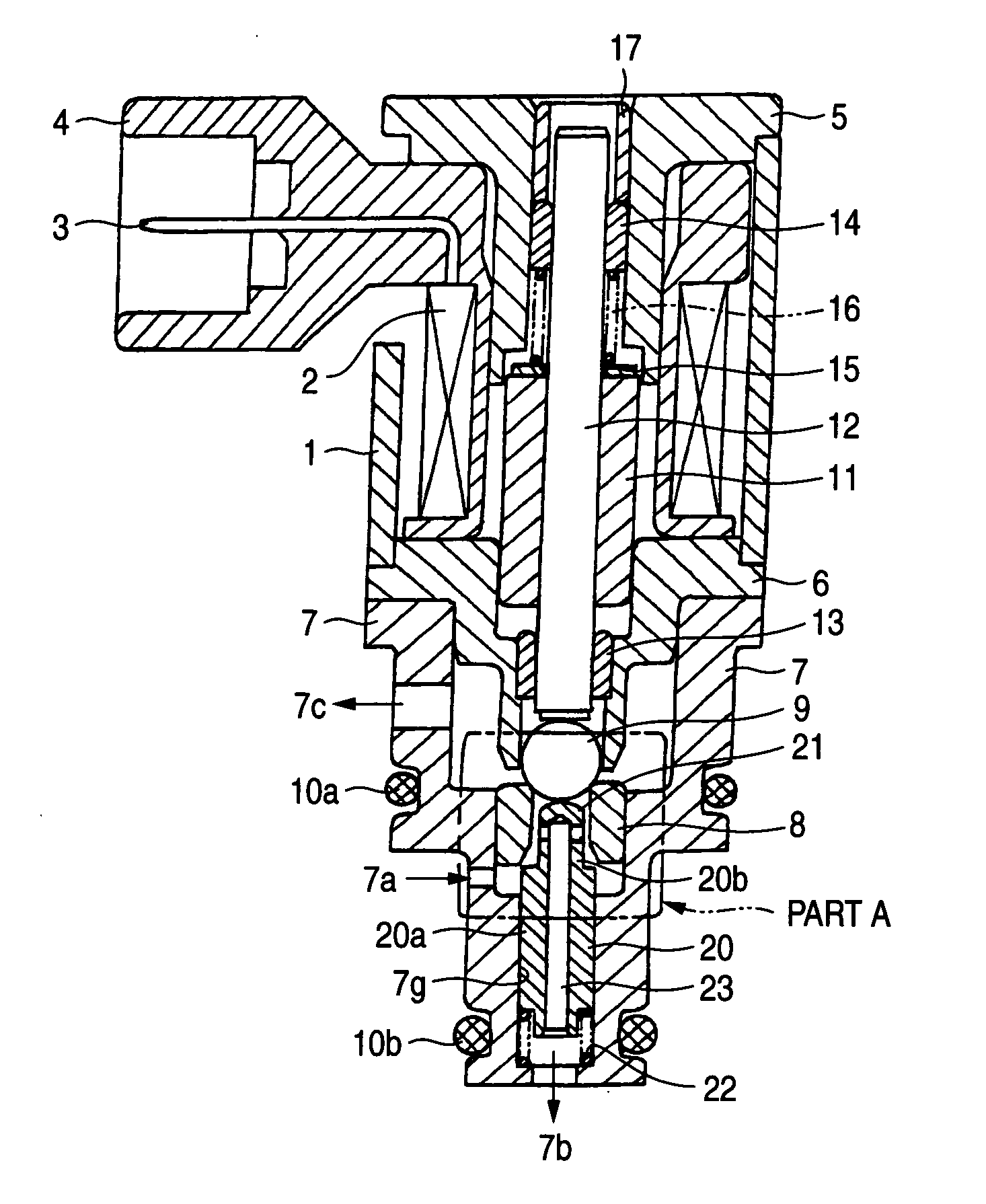
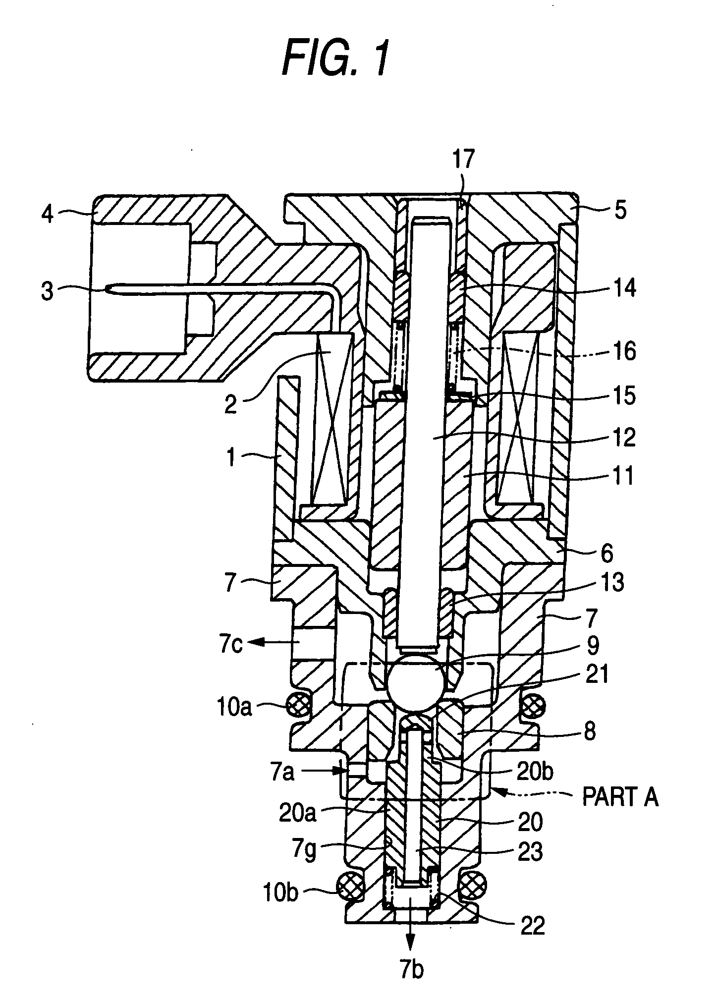
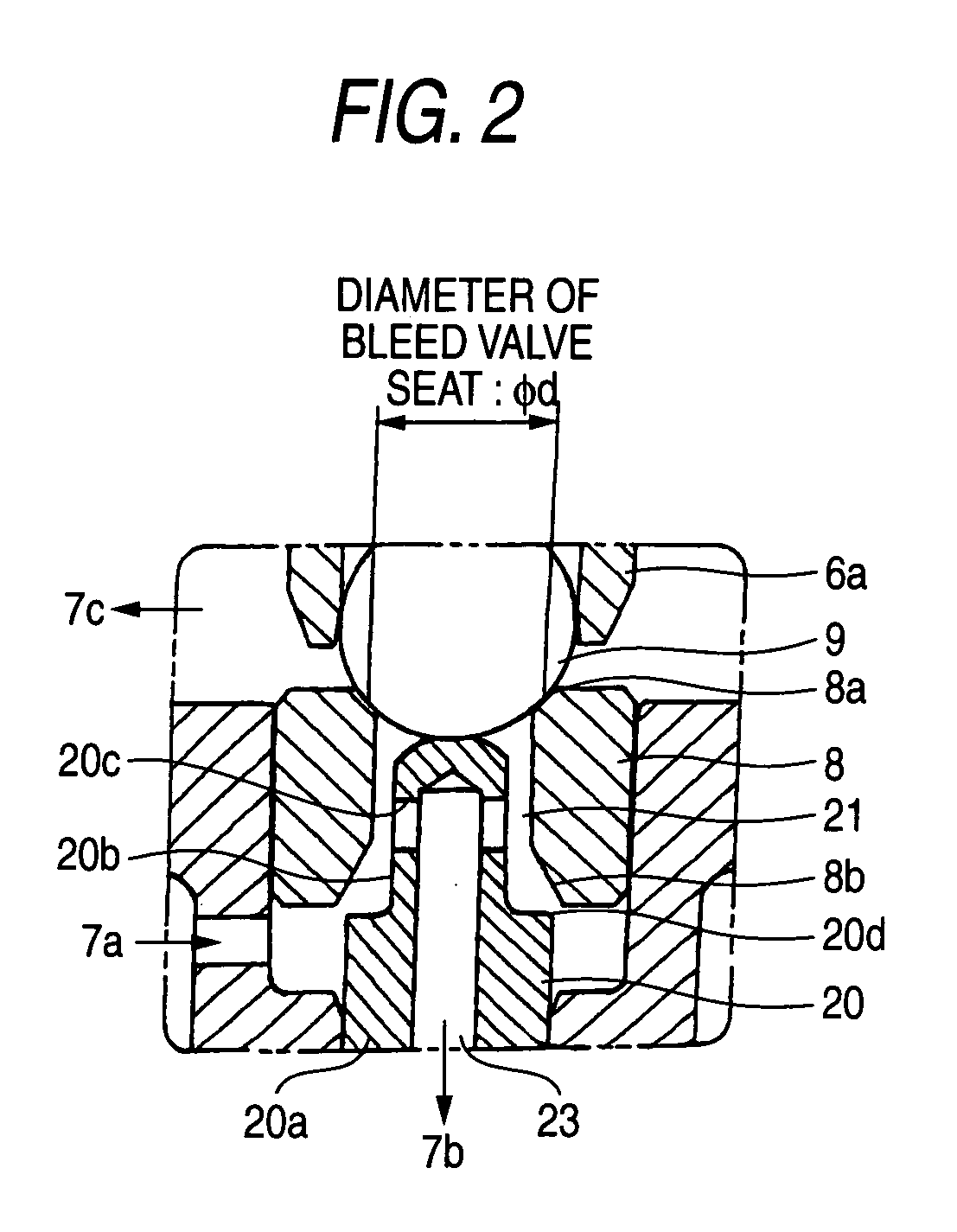
[0040]FIGS. 1-4 are sectional views of an N / H-type, three-way bleed type proportional electromagnetic valve according to a first embodiment of the present invention. FIG. 1 shows states of individual members in a non-energization state, and FIG. 2 is an enlarged view of part A in FIG. 1. Members in FIGS. 1-4 having the same or corresponding members in FIGS. 11 and 12 are given the same reference symbols as the latter and will not be described. The following description will be mainly directed to novel features.

[0041] According to the first embodiment of the invention, a stop valve element 20 is disposed in the flow passage between the input port 7a and the output port 7b of the housing 7. The stop valve element 20 is generally shaped like a cylinder and is stepped, that is, consists of a large-diameter portion 20a and a small-diameter portion 20b. The stop valve element 20 is loosely fit in a stop valve guide 7g (that is formed inside the housing 7 adjacent to the above flow passag...

embodiment 2

[0049]FIGS. 5 and 6 show an N / L-type, three-way bleed type proportional electromagnetic valve according to a second embodiment of the invention. This valve is similar in configuration to the N / H-type three-way bleed type proportional electromagnetic valve according to the first embodiment and has the same differences from it as the differences between the conventional N / L-type and N / H-type, two-way bleed type proportional electromagnetic valves that were described in the background section. The principle of operation of this N / L-type valve is similar to that of the N / H-type valve according to the first embodiment and hence will be described below only briefly. In a state that the solenoid coil 2 is not energized, as shown in FIG. 5 the stop valve sealing edge 20d of the stop valve element 20 rests on the stop valve seat portion 8b because of the force from the compressed spring 22.

[0050] On the other hand, the bleed valve element 9 is in contact with the stop valve element 20 and i...

embodiment 3

[0054]FIG. 7 is a sectional view of an N / H-type, three-way bleed type proportional electromagnetic valve according to a third embodiment of the invention which is a modification of the N / H-type, three-way bleed type proportional electromagnetic valve according to the first embodiment. In this embodiment, a guide member 24, which is employed as the stop valve guide 7g of the housing 7, is press-fit in the inner circumferential surface of the housing 7. In the first embodiment, the flow rate of leakage between the input port 7a and the output port 7b, that is, the sealability and the slidability, can be set properly by changing the settings of the radial clearance and the sealing length (i.e., axial length) of the sliding contact portion that consists of the outer circumferential surface of the stop valve element 20 and the stop valve guide 7g of the housing 7. However, the housing 7 should be re-produced each time, which is costly. In contrast, in this embodiment, by virtue of the us...


PUM


Abstract

A bleed-type proportional electromagnetic valve having an input port, output port, and ejection port is disclosed. Fluid force and pressing force, proportionate to an output pressure and a current flowing in a solenoid coil respectively, act on a bleed valve for controlling the output pressure, whereby the valve can obtain an output pressure commensurate to the flowing current by displacing the valve to a position that those forces counterbalance, wherein the valve is provided with a stop valve disposed so as to be in sliding contact with a passage between the input and output port, and in contact with or separated from a valve seat. This enable the stop valve to contact with the valve seat so as to close the input port and communicate the output port with the ejection port when controlling the output pressure to be minimum.

Description

BACKGROUND OF THE INVENTION [0001] 1. Field of the Invention [0002] The present invention relates to a three-way bleed type proportional electromagnetic valve in which the fluid force that is proportional to the output pressure and the pressing force that is proportional to the energization current of a solenoid coil act on a bleed-valve element and the bleed valve element is displaced to a position where the two kinds of force are balanced with each other, whereby the output pressure is made proportional to the energization current. [0003] 2. Description of the Related Art [0004] In hydraulic circuits of electronic control type automatic transmissions (hereinafter abbreviated as ATs) for automobiles, a bleed type proportional electromagnetic valve in which the output pressure is controlled so as to be proportional to the energization current is used to change the operating oil pressure of each operating portion of an AT. [0005] First, a description will be made of a method for usin...

Claims


Application Information

Patent Timeline
Patent Type & Authority Applications(United States)
IPC IPC(8): F15B13/044F16K11/24F16H61/00F16H61/02F16H63/02F16K31/06
CPCF16H61/0021F16K31/0637F16K31/0634F16H2061/0258Y10T137/2278Y10T137/87217
Inventor ICHINOSE, YUTAURYU, TAKUYANAKAO, KENJIONISHI, YOSHIHIKO
Owner MITSUBISHI ELECTRIC CORP
Why Eureka
Try Eureka