
Image forming apparatus and fixing device

a technology of fixing device and forming apparatus, which is applied in the direction of electrographic process apparatus, instruments, optics, etc., can solve the problems of shortening the service life of heating rubber roller, affecting the quality of image, and affecting the appearance of image quality, so as to achieve rapid and wide-ranging control of image quality and glossiness

Active Publication Date: 2005-05-26
KONICA MINOLTA BUSINESS TECH INC
View PDF4 Cites 14 Cited by
  • Summary
  • Abstract
  • Description
  • Claims
  • Application Information

AI Technical Summary

Benefits of technology

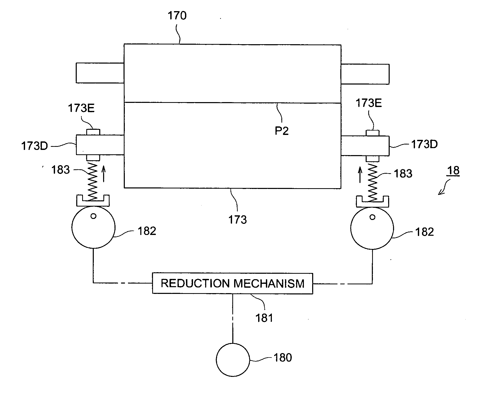
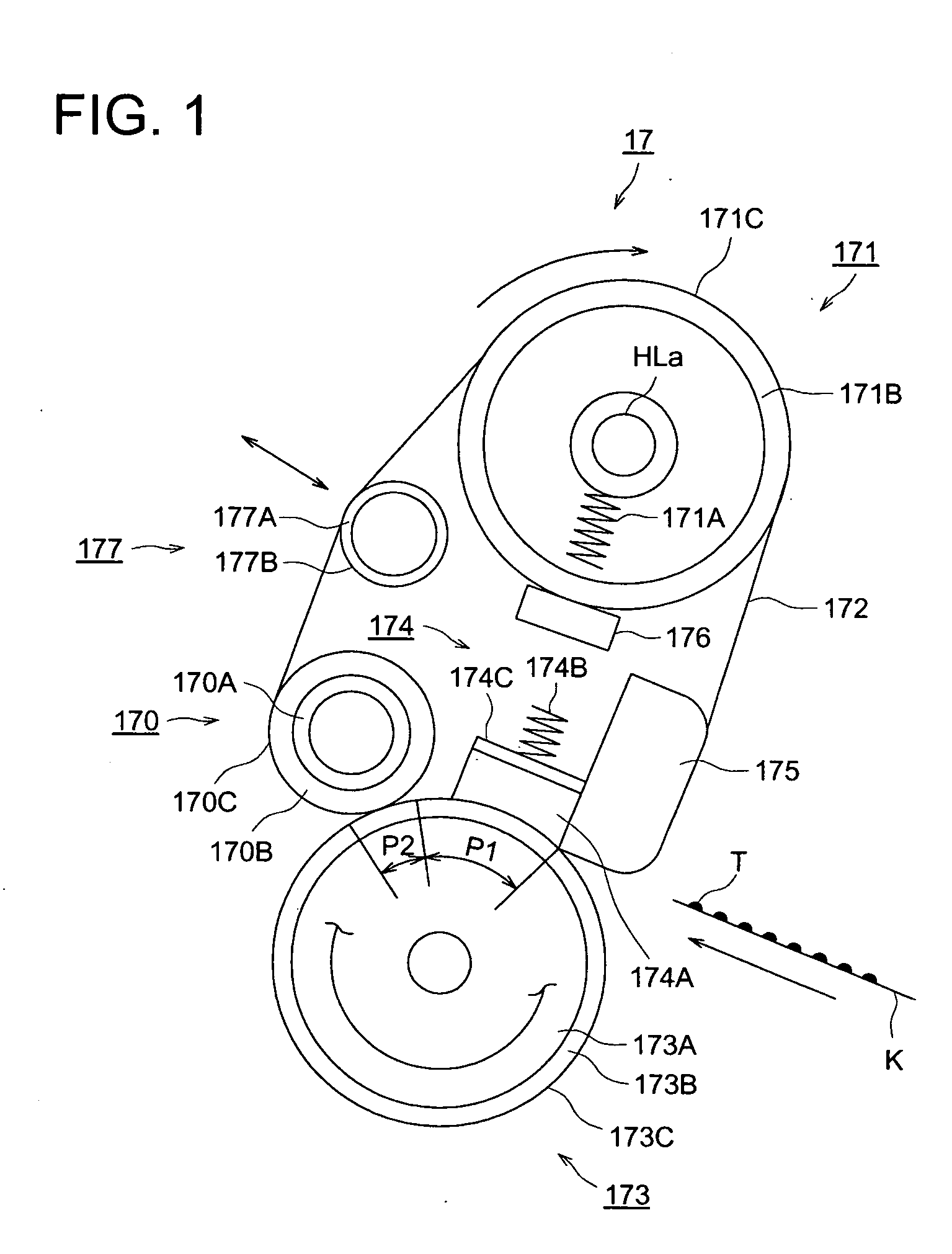
[0032] As the result, we found that we could control image quality and glossiness quickly and widely by providing the belt fixing device with a pressure changing member that changes the mean pressure on the second pressure area.
[0033] We can get high-quality images free of image misalignment by setting the belt fixing device to suppress under-offsetting in the first pressure area.

Problems solved by technology

However, in such a thermal roller fixing device, the heating rubber roller has a great heat capacity and takes a long warm-up time.
Further, the inner side of the elastic layer is heated too much.
This shortens the service life of the heating rubber roller.
This affects the other fixing performance.
This is because the fixing function is concentrated to a single point and consequently limits the exact variation of degree of glossiness.
However, by this technology using a cooling means to change the airflow rate, an exact glossiness control cannot be expected because the cooling ability is affected by the environmental temperature change.
However, this technology reduces the productivity of images of the image forming apparatus when the fixing speed is reduced.
Similarly, when a temperature change is required, it takes a lot of time to change the temperature.
This also reduces the image productivity of the image forming apparatus.
However, this technology reduces the productivity of images of the image forming apparatus as it takes a lot of time to change the temperature of the heating roller.

Method used


Image

  • Image forming apparatus and fixing device
  • Image forming apparatus and fixing device
  • Image forming apparatus and fixing device

Examples


Embodiment Construction

[0040] This invention will be described in further detail by way of an embodiment. It is to be understood that the description below is not intended to limit the technical range of claims and meanings of terms. Further, the assertive explanation of the preferred embodiments of this invention indicates the best mode and is not intended to limit the meanings of terms and technical range of claims of this invention.

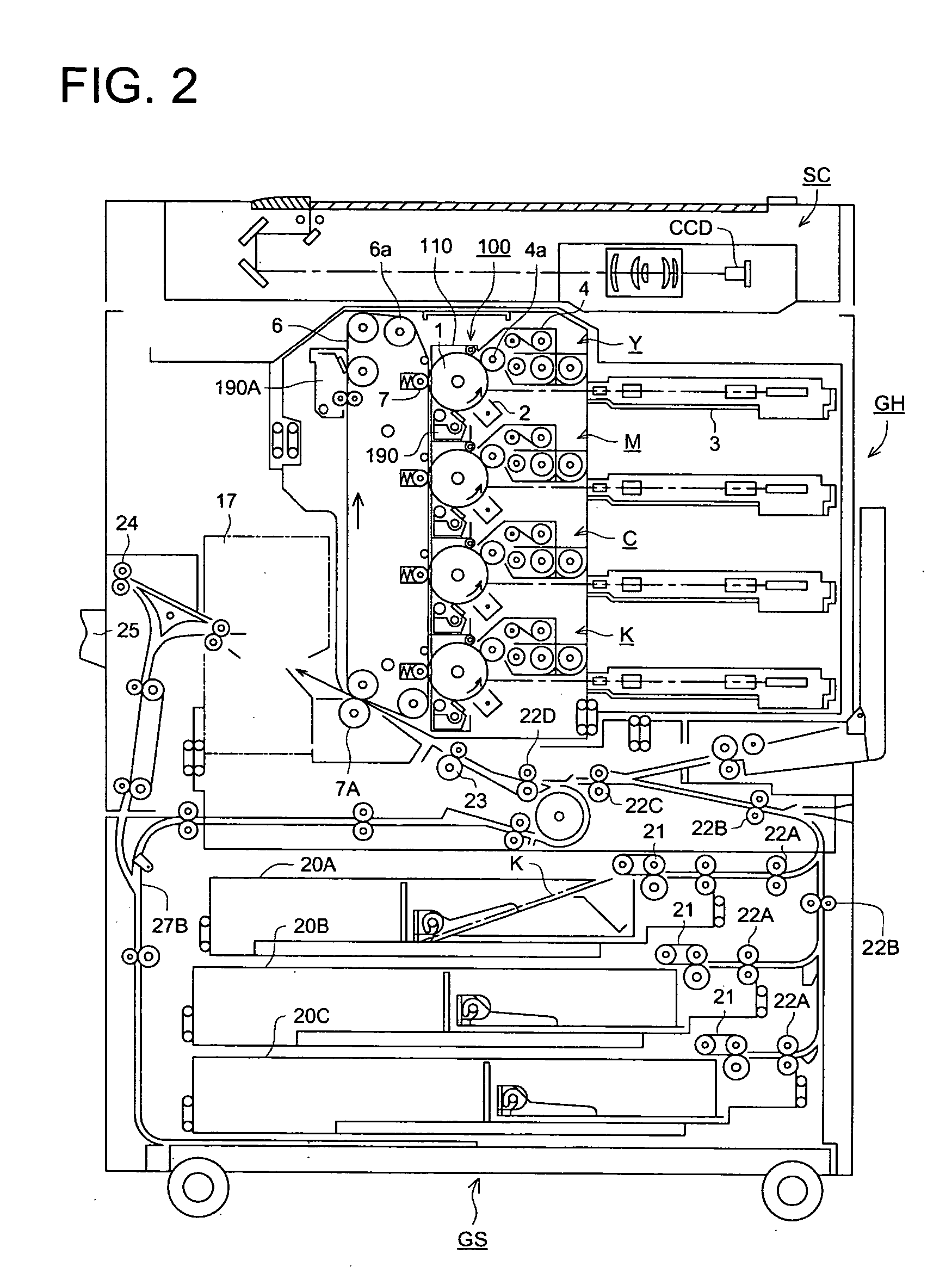
[0041] Below will be explained an image forming apparatus using a fixing device of this invention with reference to FIG. 2. FIG. 2 is a vertical sectional view of an image forming apparatus. Same reference characters designate corresponding parts in the FIG. 1 and other drawings.

[0042] Referring to FIG. 2, the image forming apparatus GS has the main an image forming apparatus body GH and an image scanning device SC mounted on the top of the main body GH.

[0043] The image forming apparatus body GH is generically called a tandem type color image forming apparatus. The main b...


PUM


Abstract

An image forming apparatus comprising a fixing roller, an endless fixing belt engaged at least with the fixing roller, and a pressing roller opposite to the fixing roller with the endless fixing belt between them; wherein the image forming apparatus is equipped with a pressure changing member for changing the mean pressure on a second pressing area against which the pressing roller pressed the fixing roller via the fixing belt in the pressure area formed by the pressing roller.

Description

BACKGROUND OF THE INVENTION [0001] This invention relates to a fixing device having a fixing belt and an image forming apparatus having the fixing belt for image formation used for an electrophotographic copying machine, printer, facsimile, and so on. [0002] Recently, the world has been increasing the demand of higher image qualities in the electrophotographic image forming apparatus such as copying machines, printers, facsimile equipment, and the like. Fixing devices of some image forming apparatus have been demanded to make images glossier or controlled. [0003] Conventionally, thermal roller fixing devices have been well known as fixing devices. A thermal roller fixing device is equipped with a heating rubber roller which has an elastic layer around it and is controlled to keep it at a preset temperature and a pressing rubber roller which is in contact with the heating rubber roller and has an elastic layer around it. A recording sheet having an unfixed toner image on it is sandwi...

Claims


Application Information

Patent Timeline
Patent Type & Authority Applications(United States)
IPC IPC(8): G03G15/20
CPCG03G15/2064G03G2215/00805G03G2215/0081
Inventor FUMA, HIROSHIYAMAZAKI, YOSHIOHAMADA, JUNICHINAGASE, HISAYOSHIONODERA, MASAHIRO
Owner KONICA MINOLTA BUSINESS TECH INC
Learn More