Signal light noise reduciton apparatus and signal light noise reduction method

a signal light and noise reduction technology, applied in the field of signal light noise reduction apparatus, can solve the problems of high accuracy, inability to achieve, and severe influence of signal light to optical noise (s/n ratio), and achieve the effect of reducing signal light noise in optical communication and reducing signal light nois

Inactive Publication Date: 2005-06-16
ALNAIR LABS CORP +1
View PDF2 Cites 17 Cited by
  • Summary
  • Abstract
  • Description
  • Claims
  • Application Information

AI Technical Summary

Benefits of technology

[0013] Specifically, this noise reduction apparatus is constructed using a carbon nanotube as the saturable absorber. This noise reduction apparatus may be arranged in the transmission path of the signal light in order to reduce signal light noise in optical communi...

Problems solved by technology

Since ASE having a random phase is added to the amplified signal light, the result is that the ratio of signal light to optical noise (S/N ratio) is severely affected.
Due to the admixture of ASE, not only is it not possible to output only prescribed signal light with high accuracy from the optical...

Method used


Image

  • Signal light noise reduciton apparatus and signal light noise reduction method
  • Signal light noise reduciton apparatus and signal light noise reduction method
  • Signal light noise reduciton apparatus and signal light noise reduction method

Examples


Embodiment Construction

[0039] An embodiment of the present invention is described below with reference to the drawings. It should be noted that in the views employed in the description for example the dimensions, shapes and arrangement relationships of the various structural constituents are only shown diagrammatically such as to enable comprehension of the present invention. Accordingly, the present invention is not restricted solely to the examples illustrated in the drawings.

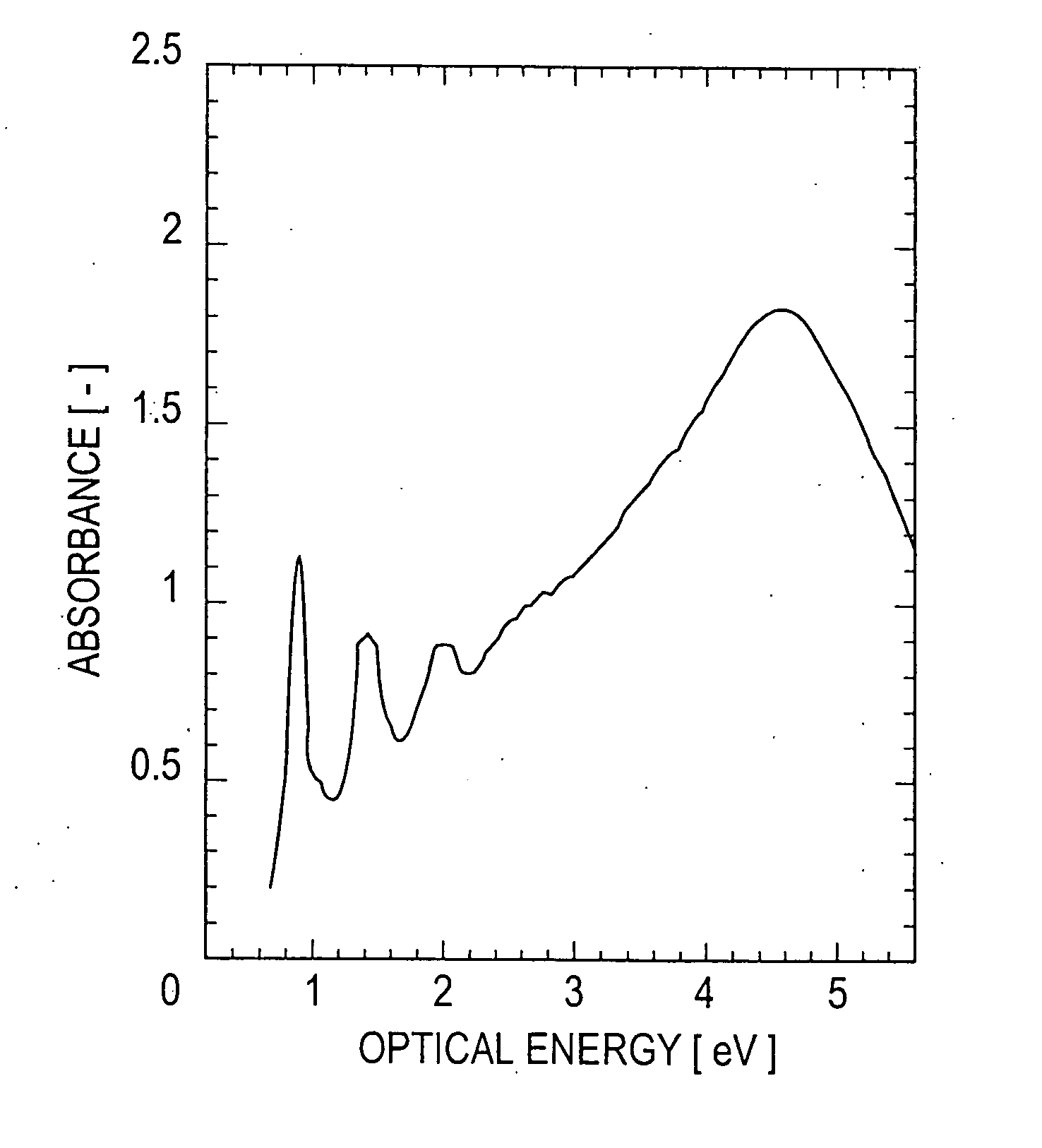
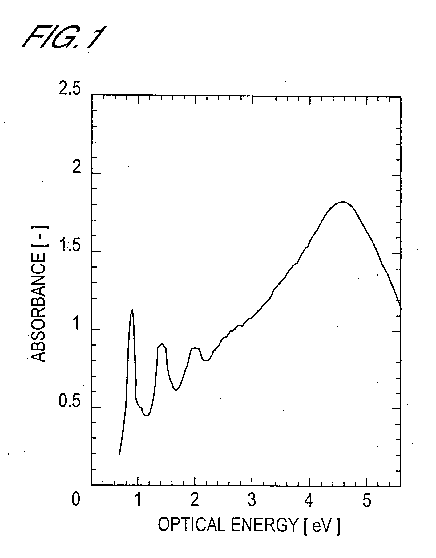
[0040] Verification of the Saturable Absorption Function of the Carbon Nanotubes

[0041] (1-1) Manufacture of Carbon Nanotubes

[0042] In this embodiment, single-wall carbon nanotubes (hereinbelow referred to as SWNT) constituted by tubular structures consisting of a single sheet of graphen formed by a six-member ring network structure of carbon atoms (C) are employed. However, it should be noted that, for the carbon nanotubes, it would also be possible to employ multi-wall carbon nanotubes (hereinbelow referred to as MWNT) constitu...


PUM


Abstract

An increase in the span of the transmission distance is aimed at by reducing unwanted ASE generated during optical communication. A carbon nanotube is employed as a saturable absorber 15 and this saturable absorber constitutes a noise reduction apparatus that has the function of cutting off or reducing transmission of unwanted ASE or the like which is of weak signal light intensity and of allowing transmission of signal light of strong light intensity. This noise reduction apparatus is arranged for example in the transmission path of signal light of a bidirectional excitation type EDFA, more precisely the apparatus is inserted in the latter stage of the EDF 40. In this way, carbon nanotubes having a saturable absorption function can be utilized in the field of optical communication.

Description

TECHNICAL FIELD [0001] The present invention relates to apparatus for reducing noise of signal light in optical communication (hereinbelow referred to as noise reduction apparatus). BACKGROUND ART [0002] With the enormous progress in optical communication technology in recent years, further increase in the span (increase in distance) of the transmission distance of signal light is desired. [0003] A method that is currently adopted with a view to increasing the span of the transmission distance consists in compensating for the attenuation of signal light intensity that accompanies transmission distance by relaying the signal light through a transmission medium such as an optical fiber by a plurality of optical amplifiers that perform optical amplification of the signal light. [0004] Optical fiber amplifiers that have attracted attention in recent years include erbium-doped fiber amplifiers (hereinbelow referred to as EDFAs) that make use of the phenomenon of stimulated emission using...

Claims


Application Information

Patent Timeline
IPC IPC(8): B82Y20/00G02F1/35H01S3/30H04B10/2507
CPCB82Y20/00G02F2202/36G02F1/3523
Inventor SAKAKIBARA, YOUICHITOKUMOTO, MADOKAACHIBA, YOHJIKATAURA, HIROMICHIJABLONSKI, MARK KENNETHTANAKA, YUICHI
Owner ALNAIR LABS CORP
Why Eureka
Try Eureka