Image reading apparatus and multi-functional apparatus

a multi-functional, image-reading technology, applied in the direction of electrographic process apparatus, instruments, optics, etc., can solve the problems of limiting the size and position of the wiring circuit board, and affecting the original transport path, so as to facilitate the elimination of failures and reduce the size of the apparatus

Active Publication Date: 2005-06-30
BROTHER KOGYO KK
View PDF8 Cites 4 Cited by
  • Summary
  • Abstract
  • Description
  • Claims
  • Application Information

AI Technical Summary

Benefits of technology

[0019] In this configuration, electrical connections between the wiring circuit board disposed on the rear face of the cover member and the apparatus can be conducted through the intermediate circuit board, and the intermediate circuit board can be placed in an end portion of the cover member. Therefore, it is possible to easily eliminate a failure which may occur in the electrical connection between the wiring circuit board and the apparatus when the size of the apparatus is reduced.

Problems solved by technology

However, a problem has been arisen in that the upper face of the upstream side of the transport path is squeezed, and the support member of the pressing member disposed in the upper face is made close to the bottom face of the transport path, thereby causing a failure in transportation of an original.
In this configuration, when the depressing direction of keys disposed on one of faces of the upstream and downstream sides of the bent cover coincides with the drawing direction of molds, the depressing direction of keys disposed on the other face does not coincide with the drawing direction of molds, and hence ribs for guiding the keys in the key depressing direction cannot be formed, thereby producing a problem in that a trouble is caused in operation of the keys on the face in which the depressing direction does not coincide with the drawing direction.
Since the cover is bent, the size and position of the wiring circuit board are restricted, and electrical connections between a control circuit board of the main unit of the apparatus and the wiring circuit board, such as signal lines interfere with the original transport path.
Consequently, there are problems such as that, in order to prevent a failure in transportation of an original from occurring, the signal lines must be fixed at intervals.

Method used


Image

  • Image reading apparatus and multi-functional apparatus
  • Image reading apparatus and multi-functional apparatus
  • Image reading apparatus and multi-functional apparatus

Examples


Embodiment Construction

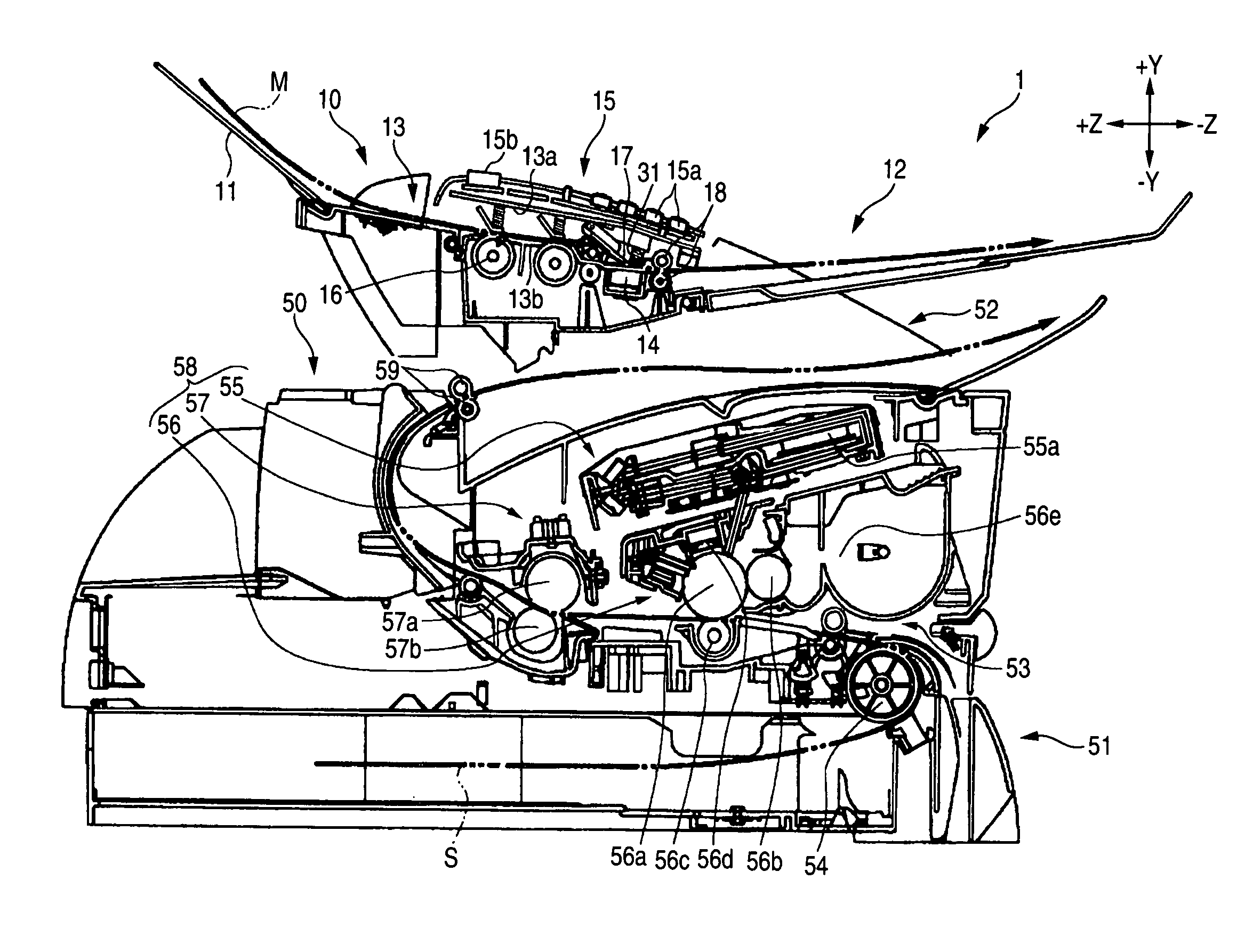
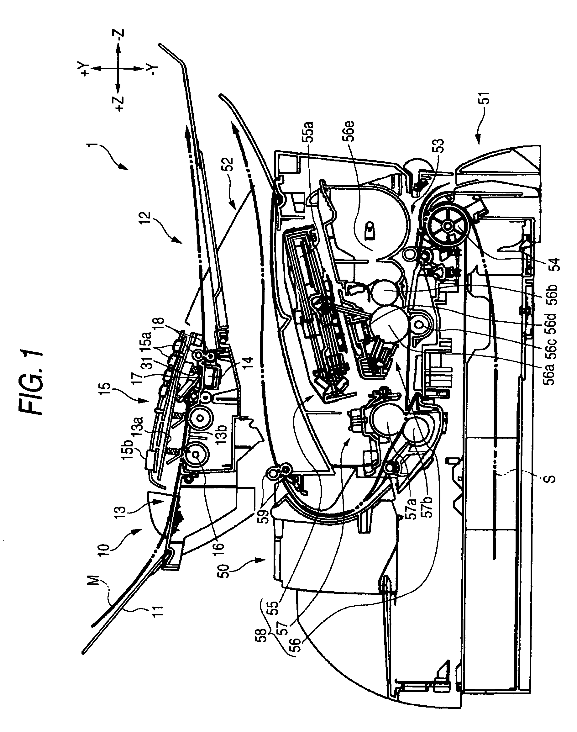
[0028] Hereinafter, an embodiment of an image reading apparatus and a multi-functional apparatus having such an image reading apparatus in which the invention is embodied will be described with reference to the accompanying drawings. Referring to FIG. 1, first, the whole configuration of a multi-functional apparatus 1 will be described. FIG. 1 is a central sectional view of the apparatus 1. Hereinafter, the directions of −Z, +Z, +Y, −Y, +X, and −X are referred to as the front direction, the back direction, the upper direction, the bottom direction, the right side direction, and the left side direction, respectively.

[0029] As shown in FIG. 1, the apparatus 1 has a configuration in which an image reading apparatus 10 for reading an image formed on a medium to be read is placed in an upper portion in the sectional view, and an image forming apparatus 50 for forming an image on a medium to be recorded is placed in a lower portion. The apparatus 1 has: a scanner function due to the imag...


PUM


Abstract

An image reading apparatus includes a transport path that is inclined downwardly as advancing from an upstream side to a downstream side, an image reading section disposed in a middle of the transport path, a cover member that is bent to cause downward inclination of a face on the downstream side of the transport path to be larger than an inclination of a face on the upstream side, a support member having a plate form, the support member disposed on a rear face of the cover member and protruding toward the upstream side from a proximity of a position where the cover member is bent in the face on the downstream side, and a pressing member in which another end is supported by the support member to cause one end to be contactable with the image reading section, thereby pressing the transported medium against the image reading section.

Description

BACKGROUND OF THE INVENTION [0001] 1. Field of the Invention [0002] The present invention relates to an image reading apparatus in which the size can be reduced, and also to a multi-functional apparatus having such an image reading apparatus. [0003] 2. Description of the Related Art [0004] Recently, a multi-functional apparatus which has an image reading apparatus, an image forming apparatus, a facsimile apparatus, and the like, and which can be used in various applications such as a scanner, a fax, a printer, and a copier is in widespread use. In an image reading apparatus mounted in such a multi-functional apparatus, in order to reduce the cost of the multi-functional apparatus, an expensive CCD image sensor is not used in an operation of reading an original serving as a medium to be read, and the reading operation is conducted with using a contact image sensor (hereinafter, abbreviated as “CIS”). [0005] A CIS has a shallower depth of field than a CCD image sensor. In order to rea...

Claims


Application Information

Patent Timeline
Patent Type & Authority Applications(United States)
IPC IPC(8): G03G15/00H04N1/00H04N1/04H04N1/12H04N1/193
CPCH04N1/121H04N2201/0456H04N2201/0422H04N1/193
Inventor NOBE, HIROSHIHAYAKAWA, ATSUSHINAGASAKA, HIDEAKI
Owner BROTHER KOGYO KK
Why Eureka
Try Eureka