Circuit for optimizing the duty cycle of a received clock transmitted over a transmission line

a transmission line and clock technology, applied in the direction of pulse generator, pulse manipulation, pulse technique, etc., can solve problems such as adversely affecting the eye pattern of group data

Inactive Publication Date: 2006-08-17
IBM CORP
View PDF9 Cites 22 Cited by
  • Summary
  • Abstract
  • Description
  • Claims
  • Application Information

AI Technical Summary

Benefits of technology

[0008] Clock signals sent with each group of data signals are detected at the receiver side. A circuit determines a maximum data eye window size for the data bits within the group recovered with the clock. Functional delay is added to the data path so a clock edge sampling the data is centered in the data eye window. The clock edge is centered in the data eye window when Setup guardband delay added to the functional delay and Hold guardband delay added to the clock are determined to be equally spaced around the sample point. Setup guardband and Hold guardband failures occur when the data with the functional delay and the Setup guardband delay, sampled with the clock, and the data with the functional delay sampled with the clock delayed by the Hold guardband delay, do not all register the same logic state when sampled over multiple clock periods. Excess edge failure indications occur when the group data signals register excessive rates of Setup guardband or Hold guardband failures which signify that the asymmetry in the duty of the clock may be adversely affecting the group data eye patterns. The Setup and Hold guardband delays are set to the maximum value that eliminates Setup and Hold guardband failures for a given Functional delay. A maximized eye pattern window is determined by setting the Functional delay to a minimum and the Hold and Setup delays to their maximums. The Functional delay is then varied across its range and Hold and Setup errors are determined. This process is iterated until a Functional delay is found with maximum values of Hold and Setup delays that do not generate Hold and Setup errors.

Problems solved by technology

Excess edge failure indications occur when the group data signals register excessive rates of Setup guardband or Hold guardband failures which signify that the asymmetry in the duty of the clock may be adversely affecting the group data eye patterns.

Method used


Image

  • Circuit for optimizing the duty cycle of a received clock transmitted over a transmission line
  • Circuit for optimizing the duty cycle of a received clock transmitted over a transmission line
  • Circuit for optimizing the duty cycle of a received clock transmitted over a transmission line

Examples


Embodiment Construction

[0022] In the following description, numerous specific details are set forth to provide a thorough understanding of the present invention. However, it will be obvious to those skilled in the art that the present invention may be practiced without such specific details. In other instances, well-known circuits may be shown in block diagram form in order not to obscure the present invention in unnecessary detail. For the most part, details concerning timing considerations and the like have been omitted inasmuch as such details are not necessary to obtain a complete understanding of the present invention and are within the skills of persons of ordinary skill in the relevant art.

[0023] Refer now to the drawings wherein depicted elements are not necessarily shown to scale and wherein like or similar elements are designated by the same reference numeral through the several views.

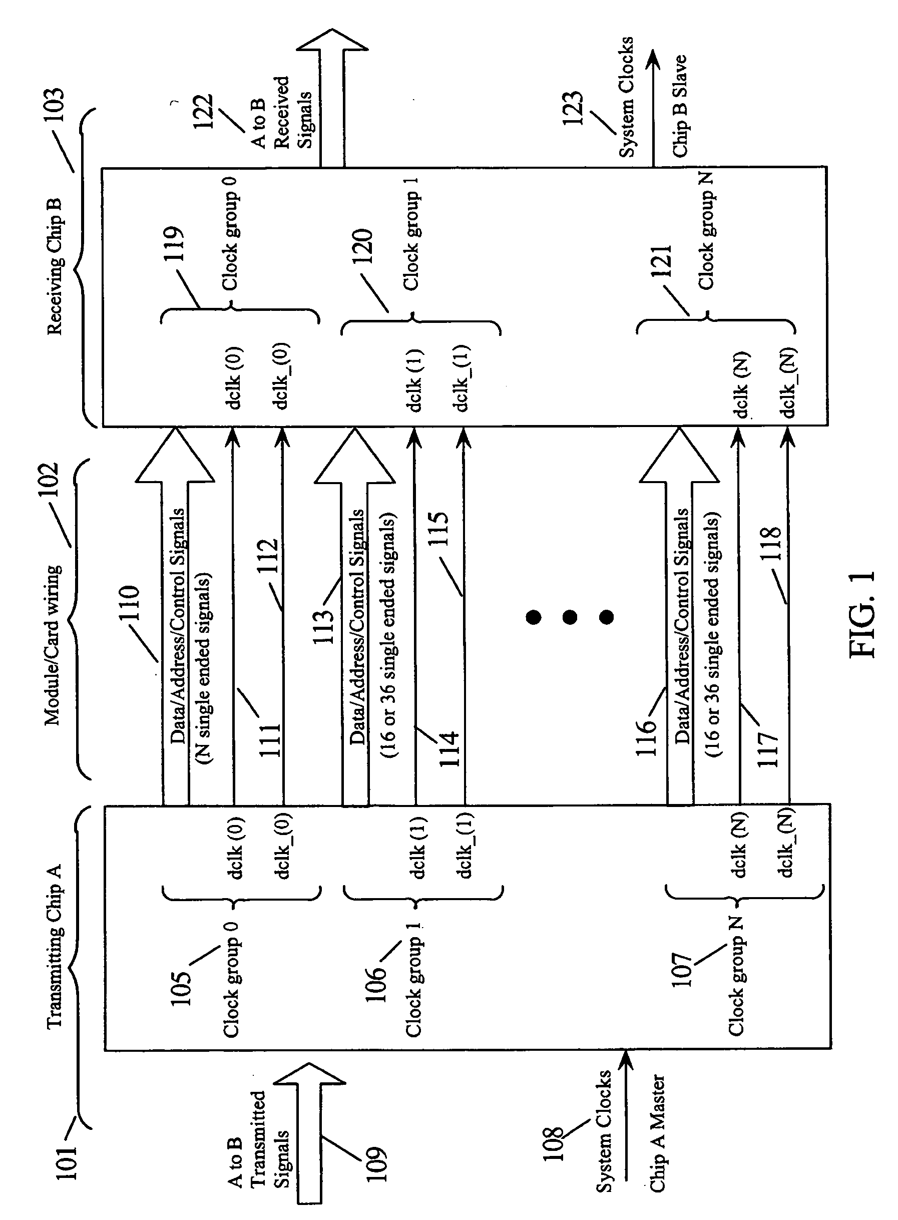
[0024]FIG. 1 is a block diagram of clock groups communicating between two chips where the signals may use pseu...


PUM


Abstract

Data signals are transmitted over transmission lines in groups to receivers in a receiving IC. Each group of data signals has a differential clock used in synchronizing and detecting the data signals. The data signal eye windows vary with timing jitter in the data signals relative to the clock edges and the asymmetry in a compensated clock signal detected from the differential clock using a duty cycle adjustment circuit. Error detection determines if the clock asymmetry is affecting the eye window of the data signals. Control signals selectively adjust the gain of differential stages generating the compensated clock to modify the duty cycle of the compensated clock. The eye window of the data signals are monitored and used as feedback to servo the control signals to optimize the duty cycle of the compensated clock signal for sampling the data signals.

Description

TECHNICAL FIELD [0001] The present invention relates in general to board level transmission line drivers and receivers, and in particular, to receiver circuits for shaping receiver transmission line signals for optimum signal detection. BACKGROUND INFORMATION [0002] Digital computer systems have a history of continually increasing the speed of the processors used in the system. As computer systems have migrated towards multiprocessor systems, sharing information between processors and memory systems has also generated a requirement for increased speed for the off-chip communication networks. Designers usually have more control over on-chip communication paths than for off-chip communication paths. Off-chip communication paths are longer, have higher noise, impedance mismatches, and have more discontinuities than on-chip communication paths. Since off-chip communication paths are of lower impedance, they require more current and thus more power to drive. [0003] When using inter-chip ...

Claims


Application Information

Patent Timeline
Patent Type & Authority Applications(United States)
IPC IPC(8): H03L7/06
CPCH03L7/0814H04L7/0008H04L7/033H04L25/0272H04L7/0041H04L7/0037
Inventor DREPS, DANIEL M.FERRAIOLO, FRANK D.REESE, ROBERT J.WIEDEMEIER, GLEN A.
Owner IBM CORP
Why Eureka
Try Eureka