Drawer guide rail system

a technology for guiding rails and drawers, applied in drawers, furniture parts, domestic applications, etc., can solve problems such as deceleration of closing motion, and achieve the effects of reducing the risk of failure of closing devices, reducing the risk of failure, and being highly toleran

Inactive Publication Date: 2013-03-28
HARN MARKETING
View PDF10 Cites 21 Cited by
  • Summary
  • Abstract
  • Description
  • Claims
  • Application Information

AI Technical Summary

Benefits of technology

[0029]The objective of the drawer guide rail system of this invention is to provide a reliably aided, quiet, controlled and decelerated drawer-closing motion with a system of a sufficiently robust design to withstand excessive drawer-closing force without the need for frequent replacements of drawer or guide rail elements.
[0030]Usage of a pivotable driver in the closing device of the guide rail system of this invention, rather than a rotating member, advantageously significantly reduces and quite possibly eliminates failure of the closing device. This is because the function of the closing device (driver) is not dependent on accurate insertion of the pull out rail guiding pin within its angular slot.
[0031]This also allows the closing device (guide rail system) to be highly tolerant of manufacturing irregularities and / or assembly errors, since as mentioned above its function is no longer dependent on insertion (accurate or otherwise) of the pull out rail guiding pin into the angular slot.
[0032]Reliable and improved function of the closing device would also result in improved efficiency in deceleration of the drawer closing motion (by the damping device and channel guide) as well as decreased likelihood of damage to the elements of the guide rail system.
[0033]Assembly and manufacture of the guide rail system of this invention are also significantly eased with this closing device design in comparison with that of the prior design.

Problems solved by technology

Thereafter, linear movement of the driver urges the sliding member to correspondingly travel along the channel guide against the resilience of the damping device, resulting in deceleration of the closing motion.

Method used


Image

  • Drawer guide rail system
  • Drawer guide rail system
  • Drawer guide rail system

Examples


Embodiment Construction

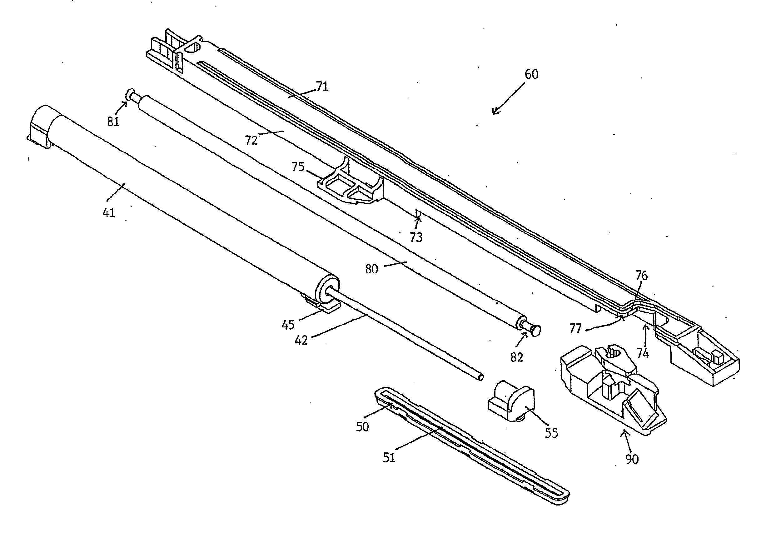
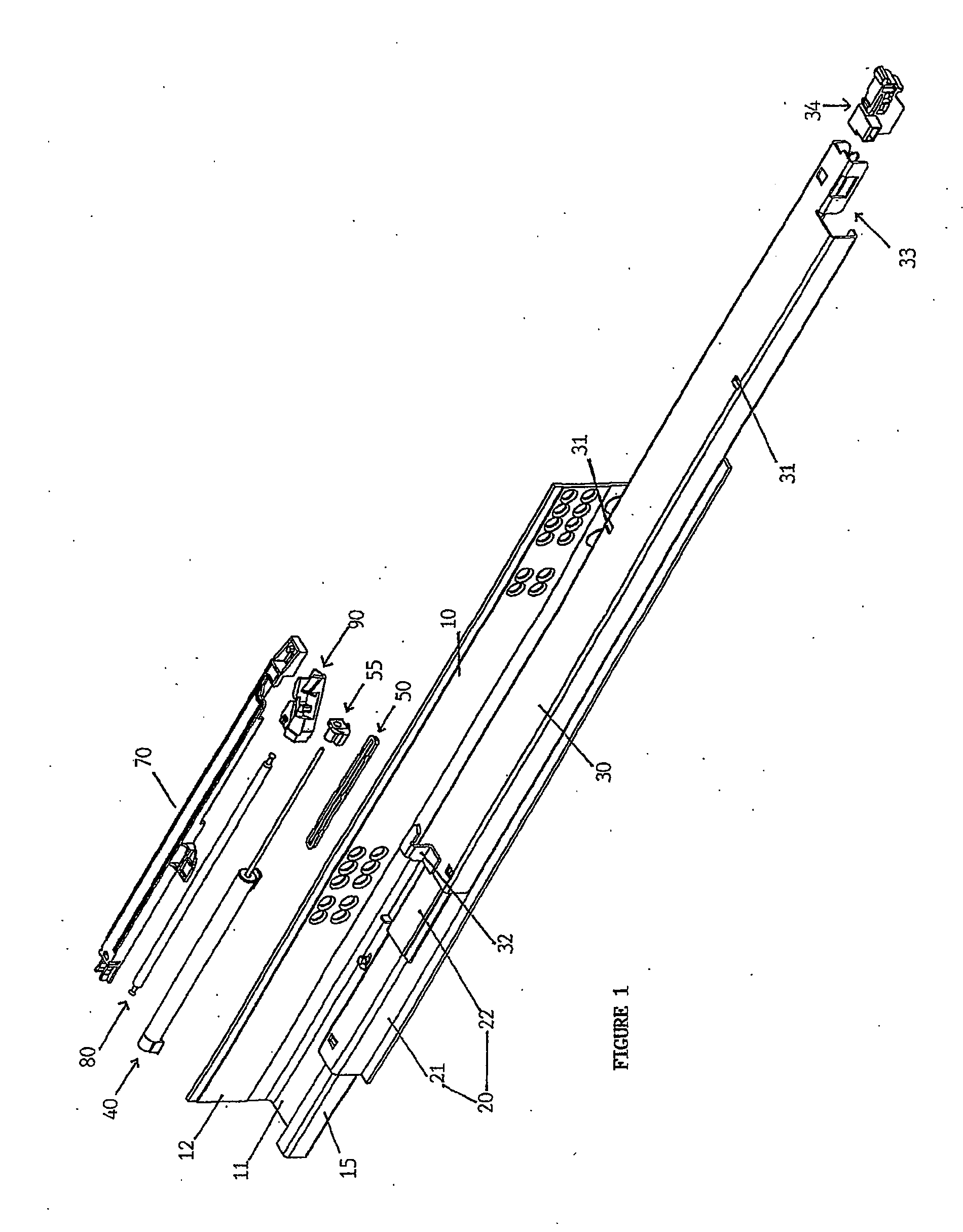
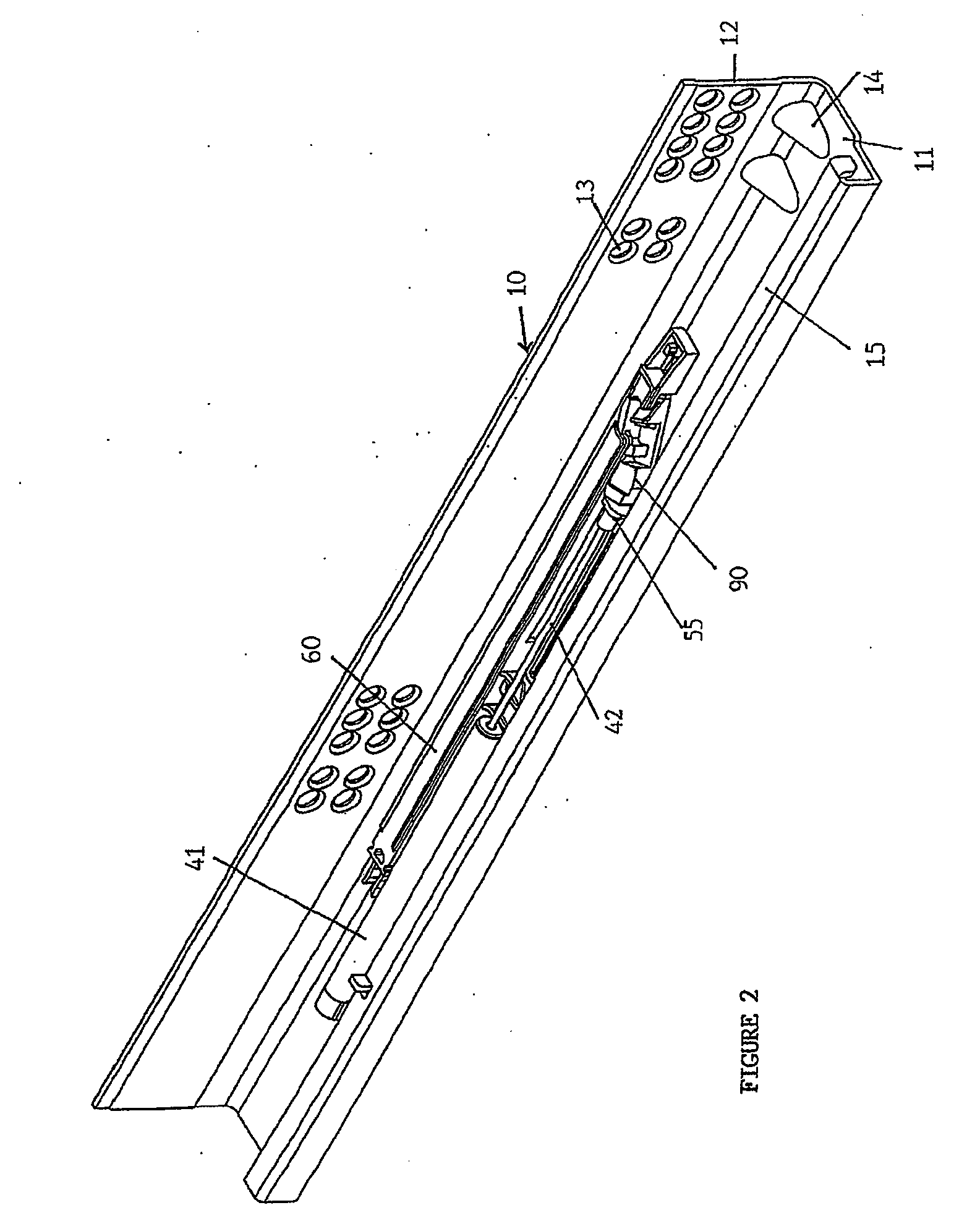
[0043]FIGS. 1 to 8 show an embodiment of a drawer guide rail system according to the present invention. This guide rail system comprises of a mounting bracket 10 for fixing the drawer to the article of furniture, the mounting bracket 10 having a fixed rail 15, an intermediate rail 20 and a pull out rail 30 secured to the drawer. The fixed rail 15 and pull out rail 30 each have a slidable housing (not shown) having a plurality of rollers, which enables the intermediate rail 20 to be slidable on the fixed rail 15 and the pull out rail 30 to be in turn slidable on the intermediate rail 20. A damping device 40 and a channel guide 50 with sliding member 55 are mounted on and along the mounting bracket 10 adjacent the fixed rail 15. Also mounted on the mounting bracket 10 is a closing device 60, which comprises of a housing 70, a resilient means 80 and a pivotable driver 90 that operatively interacts with the sliding member 55 (channel guide 50) and damping device 40 to initiate decelerat...


PUM


Abstract

A guide rail system for slidably opening and closing a drawer within an enclosure is disclosed. The system comprises a mounting bracket for fixing the system to the enclosure, the mounting bracket having a fixed rail for receiving an intermediate rail capable of sliding back and forth on the fixed rail, and a pull out rail operatively attached to the drawer and capable of sliding back and forth on the intermediate rail. A resiliently compressible damping device, channel guide with sliding member and a closing device are disposed along the mounting bracket. The pull out rail has a guiding pin on its bottom surface. The sliding member is adapted to travel along the channel guide and locate an end of the damping device that can be pushed inwardly to provide damping. The closing device comprises a housing, a resilient means, and a driver pivotally mounted with the housing and operatively connected to the resilient means. The driver is pivotable between a first locked position and a second linearly moveable position, and includes an angular slot for receiving the guiding pin and an abutment projection contactable with the sliding member. During a closing action, the pull out rail is caused to slide in a drawer-closing direction. When the guiding pin reaches and engages with the angular slot, the action of the guiding pin within the angular slot causes the driver to be pivoted from its first position to its second position where the abutment projection engages with the sliding member. Thereafter, linear movement of the driver urges the sliding member to correspondingly travel along the channel guide against the resilience of the damping device, resulting in deceleration of the closing motion.

Description

[0001]This invention relates to a drawer guide rail system.[0002]More particularly, this invention relates to a drawer guide rail system having a closing device to aid in the drawer closing motion and a damping device for deceleration of a drawer closing motion.DESCRIPTION OF THE PRIOR ART[0003]Drawer guide rails are components in common every day use, such as for drawers in desks or cabinets, and for industrial use such as pull out storage shelves at a warehouse, cash registers at a supermarket, automated teller machines at banking kiosks, electronic equipment at telephone switching stations and so on.[0004]Guide rail systems are provided for drawers to be either partially or fully opened or closed and typically consist of a bracket for fixing the system to the article of furniture, a fixed rail mounted on the bracket, a pull-out rail attached to the side of the drawer, and preferably an intermediate rail in between the fixed and pull-out rails. The intermediate rail is slidable ov...

Claims


Application Information

Patent Timeline
Patent Type & Authority Applications(United States)
IPC IPC(8): A47B88/14
CPCA47B88/047A47B2210/0091A47B88/14A47B88/467A47B88/493A47B88/487
Inventor LAM, HARN LIANLAM, HARN YAN
Owner HARN MARKETING
Why Eureka
Try Eureka