Depth control for seed planter

a seed planter and depth control technology, applied in the field of deep control of seed planters, can solve the problems of large adjustment time, difficulty in accessing the adjusting mechanism, and tendency to seize up, and achieve the effects of large mechanical advantage, robust design, and greater distance over which a disengaging action may occur

Active Publication Date: 2005-08-30
BLUE LEAF I P INC +1
View PDF8 Cites 31 Cited by
  • Summary
  • Abstract
  • Description
  • Claims
  • Application Information

AI Technical Summary

Benefits of technology

[0010]It has been recognized that the shortcomings described above with respect to the known prior art can be overcome by providing a simple cooperating coupler configuration where a moveable coupler moves along a coupling axis to engage and disengage another coupler and where the coupling axis is substantially parallel to a pivot axis of a gauge arm to which a gauge wheel is mounted. In some cases it has also been recognized that a handle member can be provided as a mounting base for the moveable coupler where the handle provides a relatively large mechanical advantage when manipulating the moveable coupler. Here, where the mechanical advantage is appreciable, in at least some cases, the force of a biasing member that biases the moveable coupler toward the other coupler may be increased to provide a more robust design. In addition, in at least some cases, the distance over which a disengaging action may occur can be greater than the distances facilitated by other depth control solutions and therefore the margin for manufacturing error can be increased appreciably and overall costs can be reduced.

Problems solved by technology

Unfortunately, most depth control mechanisms of the type described above have one or more shortcomings.
For instance, some depth control mechanisms of the above type have poorly located depth adjustments that make it difficult for an operator to access the adjusting mechanism.
Some adjusting mechanisms require an operator to use two hands to adjust disc depth and to assume awkward positions when performing adjustments.
Other adjusting mechanisms utilize a threaded shaft which takes a large amount of time to adjust and which has a tendency to seize up due to rust or become bound up due to accumulation of field debris.
Still other adjusting mechanisms utilize one or a plurality of nut and bolt pairs to facilitate adjustment—these mechanisms often require two hands and are time consuming to manipulate.
Moreover, many mechanisms require a large number of complex components that require small tolerances, are relatively expensive to manufacture and assemble and are expensive to maintain and replace when damaged.
Furthermore, some mechanisms are difficult to manipulate as the mechanical advantage afforded by the mechanism designs is less than optimal.
In addition, at least some prior mechanisms have increased the width of an associated seeding row unit disadvantageously.

Method used


Image

  • Depth control for seed planter
  • Depth control for seed planter
  • Depth control for seed planter

Examples


Embodiment Construction

[0026]One or more specific embodiments of the present invention will be described below. It should be appreciated that in the development of any such actual implementation, as in any engineering or design project, numerous implementation-specific decisions must be made to achieve the developers' specific goals, such as compliance with system-related and business related constraints, which may vary from one implementation to another. Moreover, it should be appreciated that such a development effort might be complex and time consuming, but would nevertheless be a routine undertaking of design, fabrication, and manufacture for those of ordinary skill having the benefit of this disclosure.

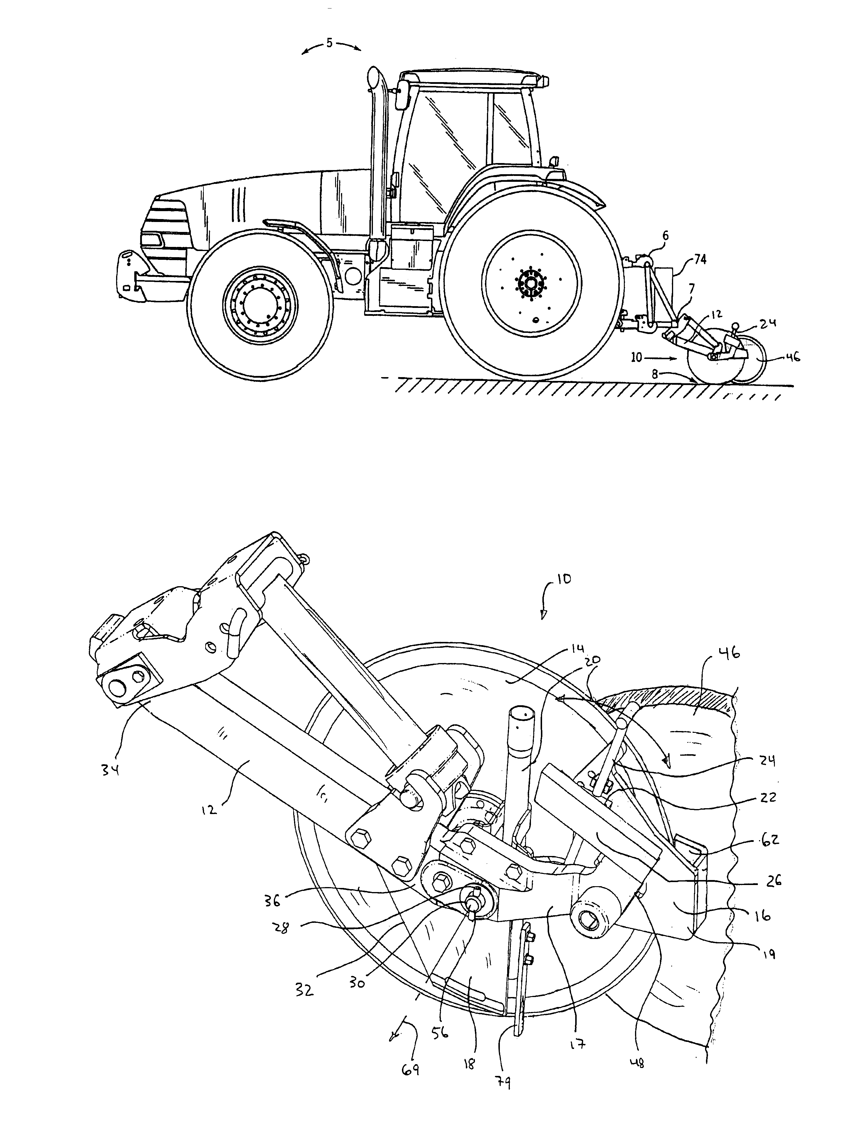
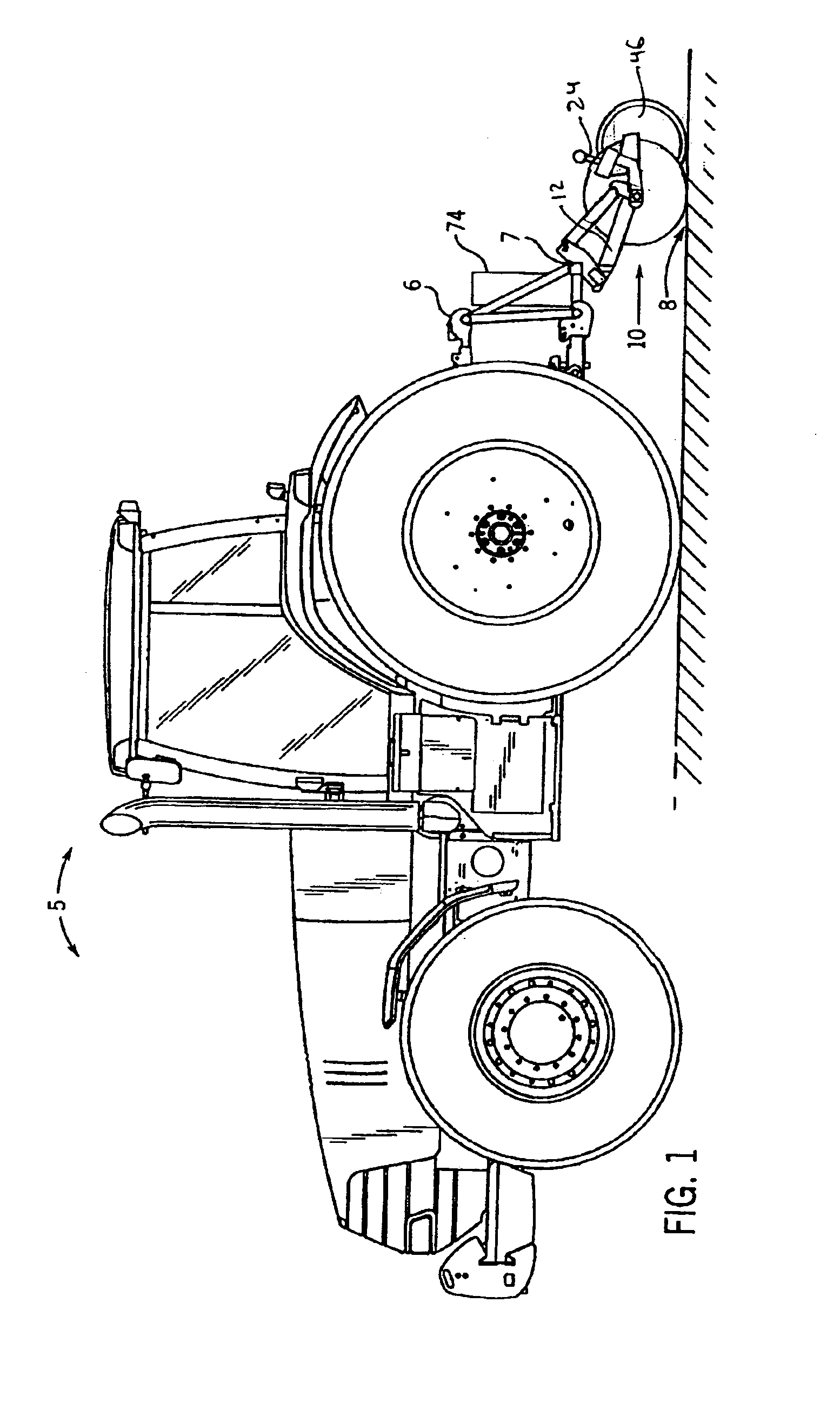
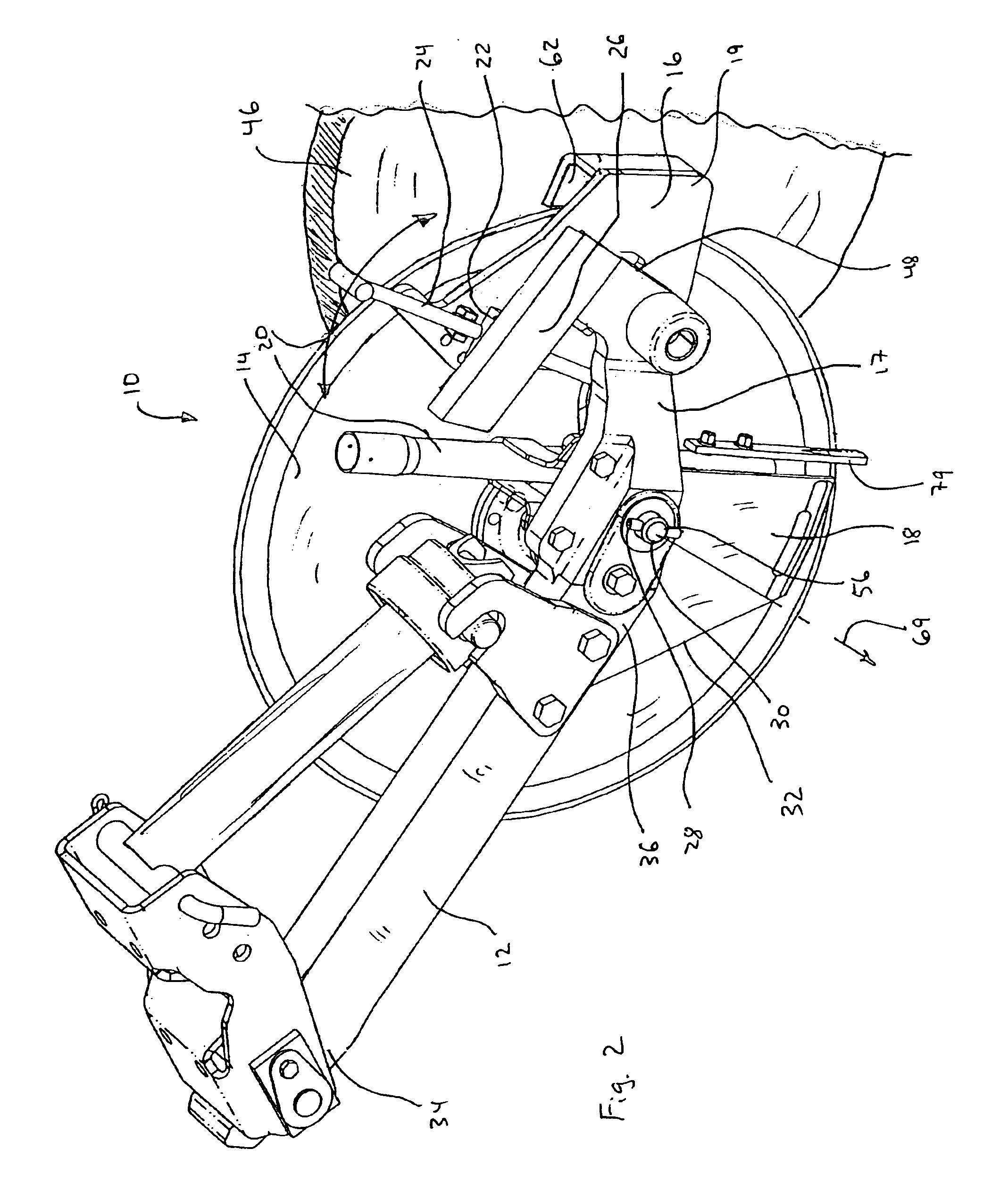
[0027]Referring now to the drawings and, more specifically, referring to FIG. 1, the present invention will be described in the context of an exemplary agricultural tractor 5 including an agricultural implement attached to a rear end 6 thereof. The implement generally includes a tool bar 7, at least on...


PUM


Abstract

A disc opener assembly connected to a tool bar linked to a vehicle for movement over the ground for opening a seed trench therein, the assembly comprising a main arm member attached to the tool bar, a disc mounted for rotation on the main arm, a gauge arm member having proximal and distal ends, the proximal end mounted for pivotal motion about a pivot axis to the main arm member, a gauge wheel mounted to the distal end of the gauge arm member, a first coupler mounted to the main arm member, a second coupler linked to the gauge arm member and juxtaposed proximate and for movement with respect to the first coupler along a coupling axis that is substantially parallel to the pivot axis, the second coupler configured to engage the first coupler when biased there against and a retainer for maintaining the first and second couplers engaged.

Description

CROSS-REFERENCE TO RELATED APPLICATIONS[0001]Not applicable.STATEMENT REGARDING FEDERALLY SPONSORED RESEARCH OR DEVELOPMENT[0002]Not applicable.BACKGROUND OF THE INVENTION[0003]This invention relates generally to agricultural planting equipment and more particularly to a disc opener assembly for a seed planter.[0004]This section of this document is intended to introduce various aspects of art that may be related to various aspects of the present invention described and / or claimed below. This section provides background information to facilitate a better understanding of the various aspects of the present invention. It should be understood that the statements in this section of this document are to be read in this light, and not as admissions of prior art.[0005]Efficient crop growth requires that seed be planted in different manners that depend at least in part upon soil conditions, fertilizer employed, seed type and anticipated weather and sun exposure conditions. To this end, a see...

Claims


Application Information

Patent Timeline
Patent Type & Authority Patents(United States)
IPC IPC(8): A01C5/00A01C5/06A01C7/20A01C7/00
CPCA01C5/064A01C7/203
Inventor MURRAY, TIMOTHY ALLENDISRUD, AARON ORALPEDERSON, NICHOLAS DEANHUWE, DANIEL JOHN
Owner BLUE LEAF I P INC
Why Eureka
Try Eureka