In-ceiling zone cabling enclosure

a cabling enclosure and ceiling-zone technology, which is applied in the direction of electrical apparatus casings/cabinets/drawers, lighting conductor installation, coupling device connection, etc., can solve the problems of insufficient structural strength of enclosures of the type described, inability to efficiently support weight, and inability to provide adequate structural strength to enable proper operation, etc., to achieve convenient conversion, maintain proper air flow, and strong structural design

Active Publication Date: 2010-09-14
PANDUIT
View PDF9 Cites 31 Cited by
  • Summary
  • Abstract
  • Description
  • Claims
  • Application Information

AI Technical Summary

Benefits of technology

[0007]The present invention comprises a telecommunications system enclosure adapted to be installed near user workstation, and in the air handling space between the natural ceiling and a drop ceiling in a work area. The enclosure accommodates active and passive network equipment, and the cables to, from and in the enclosure. Equipment mounting brackets and an equipment mounting plate are attached to the inside of an access door assembly that pivots between a closed and an open position. Active and passive equipment, or in other embodiments, passive equipment only, is attached to the mounting brackets and plate. A thermal management system, including air intake vents, an air dam and an air exhaust fan assembly, provides cooling air to the active equipment in the enclosure, and exhausts heated air from the enclosure in a direction away from the cooling air intake vents. A cable routing and slack management system, including a horizontal slack management tray with shear-forms for attaching cable bundles to the slack management tray, manages cable slack within the enclosure without the use of additional cable managers. The cable management system also contributes to thermal management and maintaining proper air flow through the enclosure by keeping the cables in the enclosure out of the vertical channels comprising the active equipment ventilation path. The enclosure also has a robust structural design, including reinforced pivotal mounting structures between the moveable access door assembly and the enclosure, support for additional equipment weight with gas piston dampers controlling the opening speed of the access door assembly, and a configuration enabling front accessible moves, adds and changes. The enclosure is also adapted to be readily converted from a passive to an active network equipment enclosure by inserting an exhaust fan assembly in the enclosure.

Problems solved by technology

Presently available in-ceiling zone cabling enclosures are not readily adapted to support the weight of additional switching and routing equipment necessary to support a typical workstation.
Nor are presently available enclosures of the type described capable of efficiently directing the flow of the air in the enclosure and dissipating heat generated by the switching and other equipment located within the enclosure.
Presently available enclosures also fail to provide sufficient structural strength to enable the proper and efficient management of the multitude of cables entering, connecting, and leaving the enclosure.
A further need also exists for an enclosure that includes structure that provides room for additional cables, that allows the cables to be efficiently organized and installed pinch free, and that doesn't allow the cables in the enclosure to interfere with the thermal management air flow pattern inside the enclosure.

Method used


Image

  • In-ceiling zone cabling enclosure
  • In-ceiling zone cabling enclosure
  • In-ceiling zone cabling enclosure

Examples


Embodiment Construction

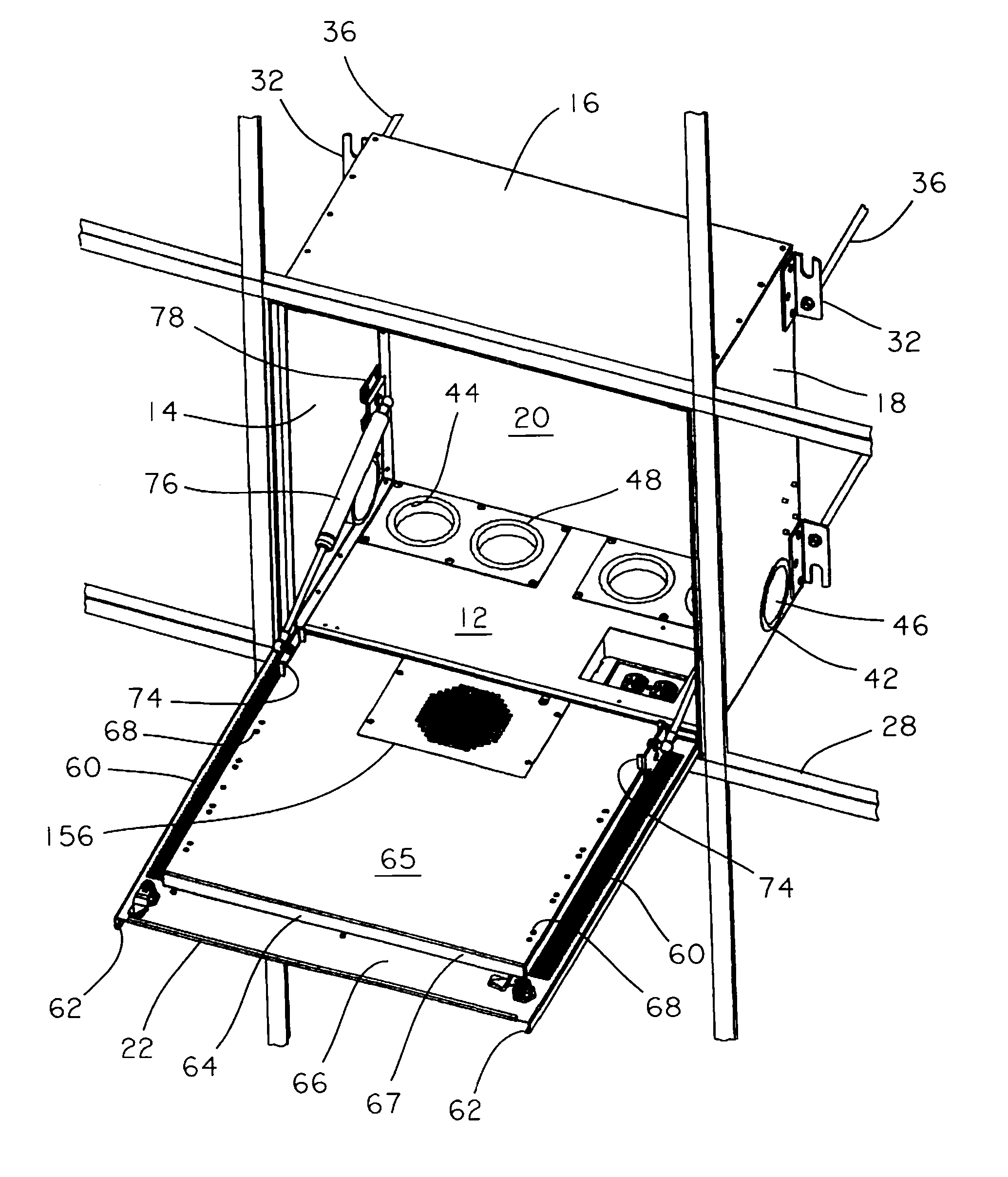
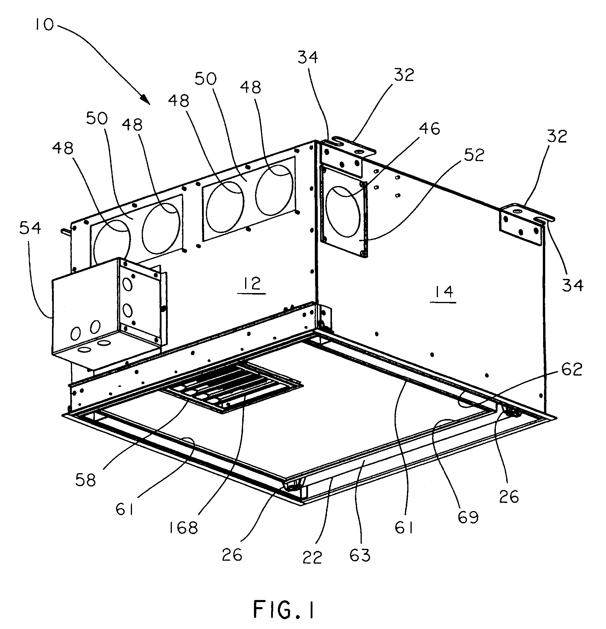
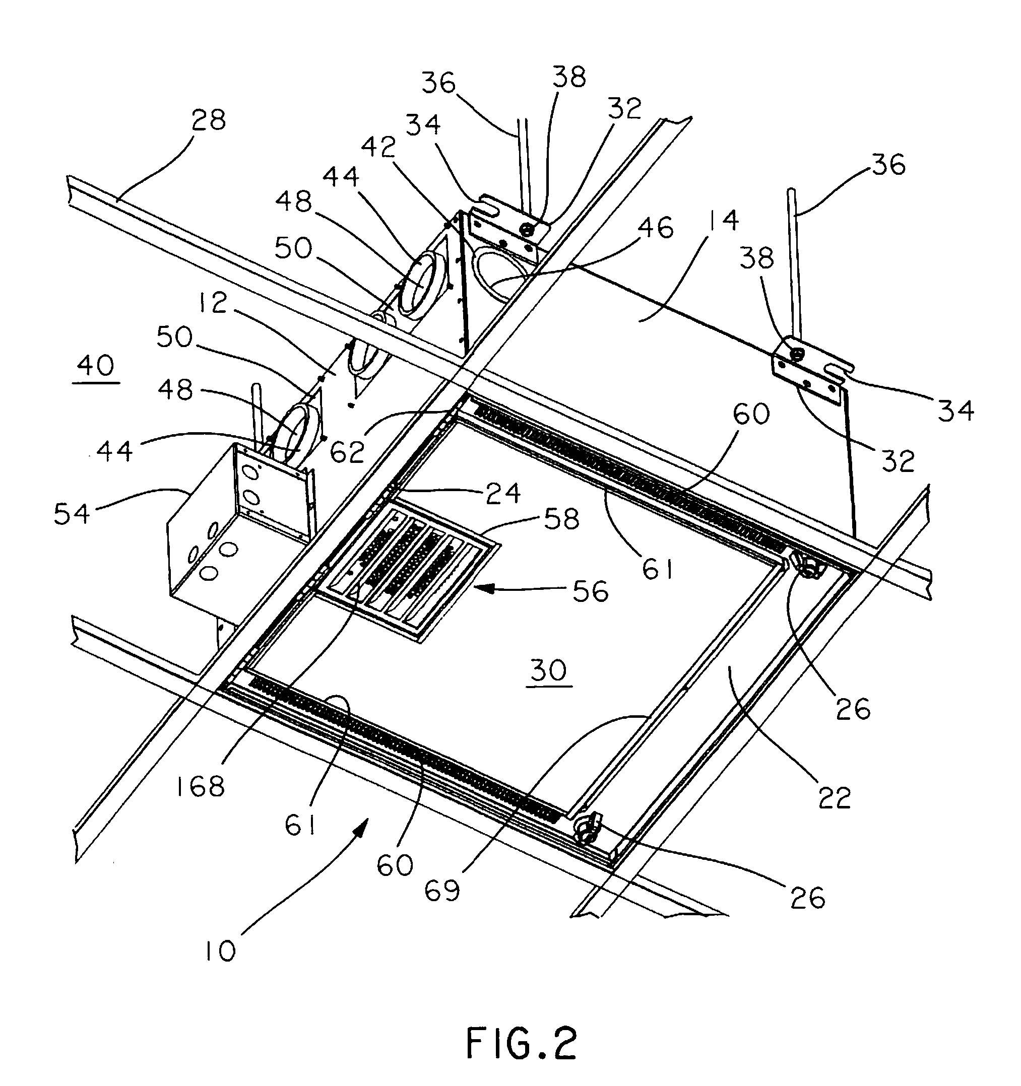
[0026]Referring to FIG. 1 an embodiment of the in-ceiling zone cabling enclosure of the present invention, for both active and passive equipment, is generally designated by the numeral 10. Enclosure 10 is bounded by four upstanding walls: rear wall 12, side wall 14, front wall 16 and side wall 18, that provide a generally square shape to the enclosure and create a volume in the enclosure. Enclosure 10 also is bounded by a top panel 20 attached to each of the walls 12, 14, 16 and 18, and an access door assembly 22 is pivotally attached to the bottom of rear wall 12 by means of hinges 24 (FIG. 2) or any other suitable pivotal attachment mechanisms as are known in the art, such as the hinge pin shown in FIG. 16. In one embodiment, access door assembly is pivotally attached to opposed side walls 14 and 18 (FIGS. 4, 16). Access door assembly 22 is held in its closed position against the bottom edges of walls 12, 14, 16 and 18 by a pair of wing nut operated latch assemblies 26. In the ill...


PUM


Abstract

An in-ceiling cabling enclosure for supporting communications network equipment and cables interconnecting the network equipment including a front wall, a rear wall, and two side walls extending between the front wall and the rear wall creating a volume inside the enclosure. An access door assembly is pivotally connected to either the rear wall or the two side walls. An equipment mount plate is attached to an interior portion of the access door assembly, and opposed equipment mount rails are removably attached to the equipment mount plate. A cable slack management tray extends between the opposed equipment mount rails, and the slack management tray has a surface adapted to support and maintain the position and the contour of cable bundles located in the enclosure. A thermal management system is also disposed in the housing to provide efficient exhaust of hot air generated by active equipment in the enclosure to the space outside of the enclosure.

Description

FIELD OF THE INVENTION[0001]The present invention relates to an in-ceiling zone cabling enclosure utilized in routing and distributing cables in a building to user work stations and, in particular, to an in-ceiling cabling enclosure that provides a robust structural design for supporting network equipment, a thermal management system that optimizes air flow through the enclosure for maximum heat dissipation and hot air evacuation, and efficient cable routing and slack management.BACKGROUND OF THE INVENTION[0002]Workspaces in buildings today consist of multiple electrical and electronic communication devices, such as computers, telephones, and the like that may be integrally connected to one another, and at the same time are electrically connected, wireless or by wire, to servers, databases and other equipment located at the central place in the building. These servers, databases and the like store, generate and transmit data, voice and video signals that must be transmitted through ...

Claims


Application Information

Patent Timeline
Patent Type & Authority Patents(United States)
IPC IPC(8): H01J5/00
CPCH02G3/16H02G3/20H02G3/381
Inventor BRAVO, REYSWETT, BRETT A.VOGEL, MARK A.
Owner PANDUIT
Why Eureka
Try Eureka