Bar system

a bar system and bar system technology, applied in the field of bar systems, can solve the problems of increasing costs and hindering design from breaking engagement means, and achieve the effect of more cost-efficient bar systems and smaller material consumption

Active Publication Date: 2013-03-19
BYGG OCH MILJOTEKNIK GRANAB
View PDF1 Cites 34 Cited by
  • Summary
  • Abstract
  • Description
  • Claims
  • Application Information

AI Technical Summary

Benefits of technology

[0009]Such a design having engagement means which are pressed towards the level adjustment means during application of the bars to the level adjustment means have several advantages. Firstly, such a design makes it possible to produce engagement means which are stronger than engagement means which are pressed away from the level adjustment means, since due to manufacturing reasons such a design makes it possible to have a larger joint between each engagement means and the level adjustment means. In addition, such a design is more robust also since the engagement means are pressed in abutment against the level adjustment means before a force large enough for breaking the engagement means is applied. Thus, the design hinders from breaking engagement means while assembling the bar system. A level adjustment means having a broken engagement means is unusable and has to be replaced with an unbroken one, which increases the costs. Consequently, the design also results in a more cost-efficient system.
[0025]According to an exemplary embodiment, said retaining means comprises two sets of protrusions, each of which comprises at least two separate protrusions, which protrusions and sets of protrusions are oppositely arranged in relation to each other, and which protrusions are arranged to abut on opposite parts of a lateral side of the dampening means. Such two protrusions may together have an extension along the circumference of the dampening means that is smaller than an extension of an oblong protrusion along the whole part of the circumference of the dampening means which is substantially perpendicular to the shanks of the bars. Thus, the consumption of material may be smaller resulting in a more cost-efficient bar system.

Problems solved by technology

Thus, the design hinders from breaking engagement means while assembling the bar system.
A level adjustment means having a broken engagement means is unusable and has to be replaced with an unbroken one, which increases the costs.

Method used


Image

  • Bar system
  • Bar system
  • Bar system

Examples


Embodiment Construction

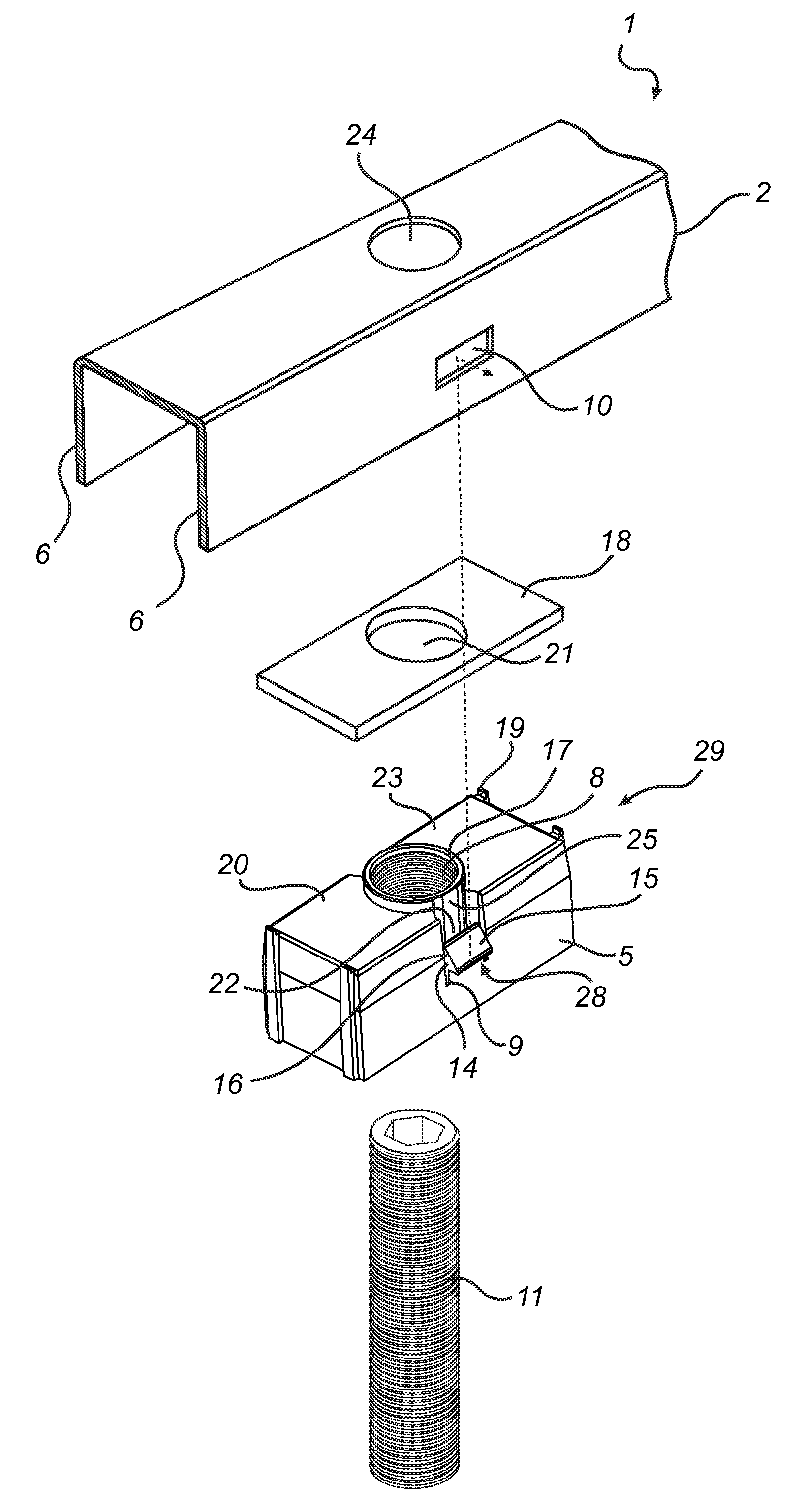
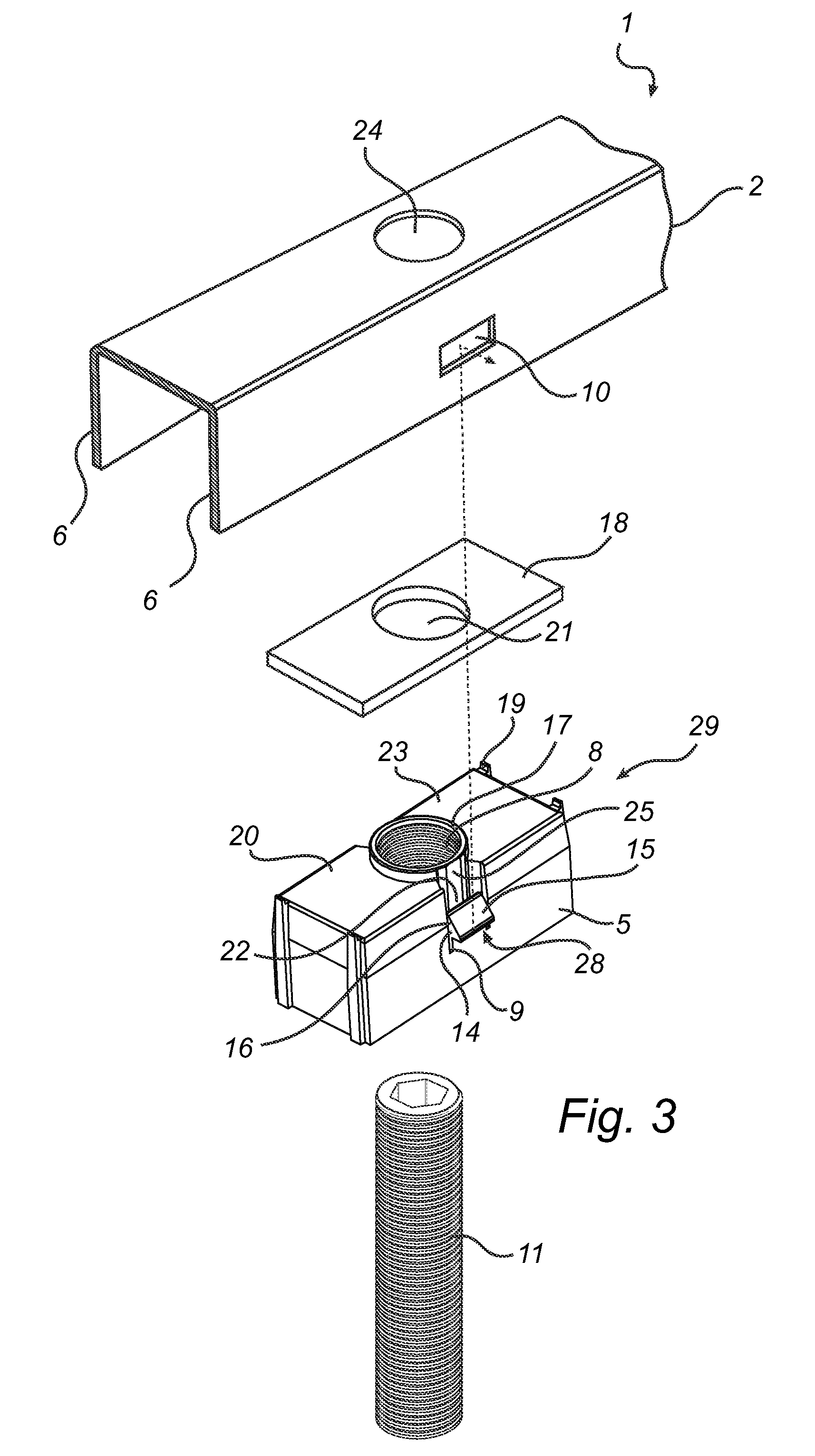
[0036]The embodiments of the invention are described and illustrated throughout this application as standing on a support structure such as a floor. Hence, words as “upper” and “lower” are intended to have their ordinary meaning in a vertical direction. Thus, an upper end is an end that is father away from the support structure than a lower end. However, the bar system may also be used on other types of support structures such as walls or ceilings. In such cases “upper” is to be interpreted as farther away from the support structure than “lower”. Thus, “an upper side” is the side facing away from the support structure in use of the system and “a lower end” is the end which is nearest the support structure in use of the system. Words as “above” and “under” is intended to be interpreted in a similar way.

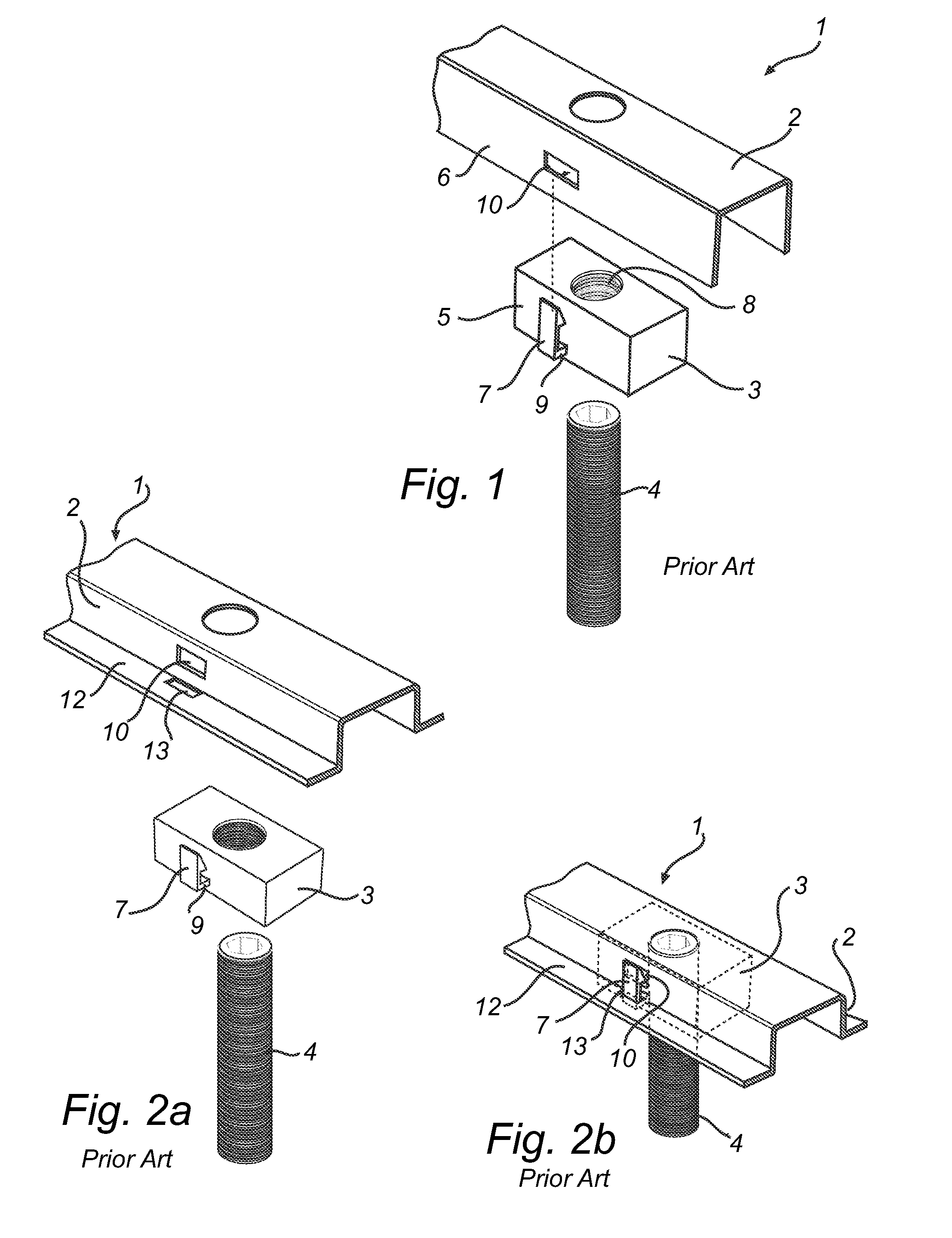
[0037]FIGS. 1, 2a, and 2b illustrates each, a part of a bar system 1 comprising a bar 2, a rectangular block 3, and a threaded support rod 4 according to prior art. In FIG. 1 the bar 2...


PUM


Abstract

A bar system for building, the system provided with a plurality of bars, a level adjustment mechanism, and a dampener. Each of the bars having a recess positioned in a shank portion, with bars being adapted in use to at least partly enclose the level adjustment mechanism. The level adjustment mechanism including level adjustable projections adapted to project from the bars against a support structure, and provided with a surface which extends in a longitudinal direction of the bars, as seen in the use of the system, and with engagement adapted for engagement with recess. The shank, which the recesses that is adapted to engage with the engagement, is adapted to press the engagement towards level adjustment during application of the bars to the level adjustment, and recess is adapted to allow the engagement for moving resiliently back for engagement with recess in an interconnected position.

Description

CROSS-REFERENCE TO RELATED APPLICATION[0001]This application is the U.S. national phase of PCT Appln. No. PCT / EP2009 / 066196 filed on Dec. 2, 2009, the disclosure of which is incorporated in its entirety by reference herein.FIELD OF THE INVENTION[0002]The present invention relates to a bar system for building constructions, comprising bars, level adjustment means, and dampening means. Each of the bars comprises a recess, positioned in a shank of each bar. The bars are adapted in use to at least partly enclose the level adjustment means. The level adjustment means comprises level adjustable projections, which are adapted to project from the bars against a support structure. The level adjustment means are provided with a surface which extends in a longitudinal direction of the bars, as seen in the use of the system, and with engagement means adapted for engagement with said recess.BACKGROUND OF THE INVENTION[0003]In many cases it is suitable to mount floors, interior walls or the like ...

Claims


Application Information

Patent Timeline
Patent Type & Authority Patents(United States)
IPC IPC(8): E04G1/22
CPCE04F15/0247E04F15/02458E04F2015/02061E04F15/02044
Inventor BLOM, FREDRIKBLOM, KENT
Owner BYGG OCH MILJOTEKNIK GRANAB
Why Eureka
Try Eureka