Chemical feeding device

a feeding device and chemical technology, applied in the direction of instruments, packaging goods, de-stacking articles, etc., can solve the problems of increasing manufacturing cost and part management cost, remarkably difficult to carry out maintenance such as cleaning, exchanging parts, etc., and reducing the generality and convenience of use, so as to save cost

a feeding device and chemical technology, applied in the direction of instruments, packaging goods, de-stacking articles, etc., can solve the problems of increasing manufacturing cost and part management cost, remarkably difficult to carry out maintenance such as cleaning, exchanging parts, etc., and reducing the generality and convenience of use, so as to save cost

US20050145644A1Inactive Publication Date: 2005-07-07PHC HLDG CORP

Image

  • Chemical feeding device
  • Chemical feeding device
  • Chemical feeding device

Examples


Embodiment Construction

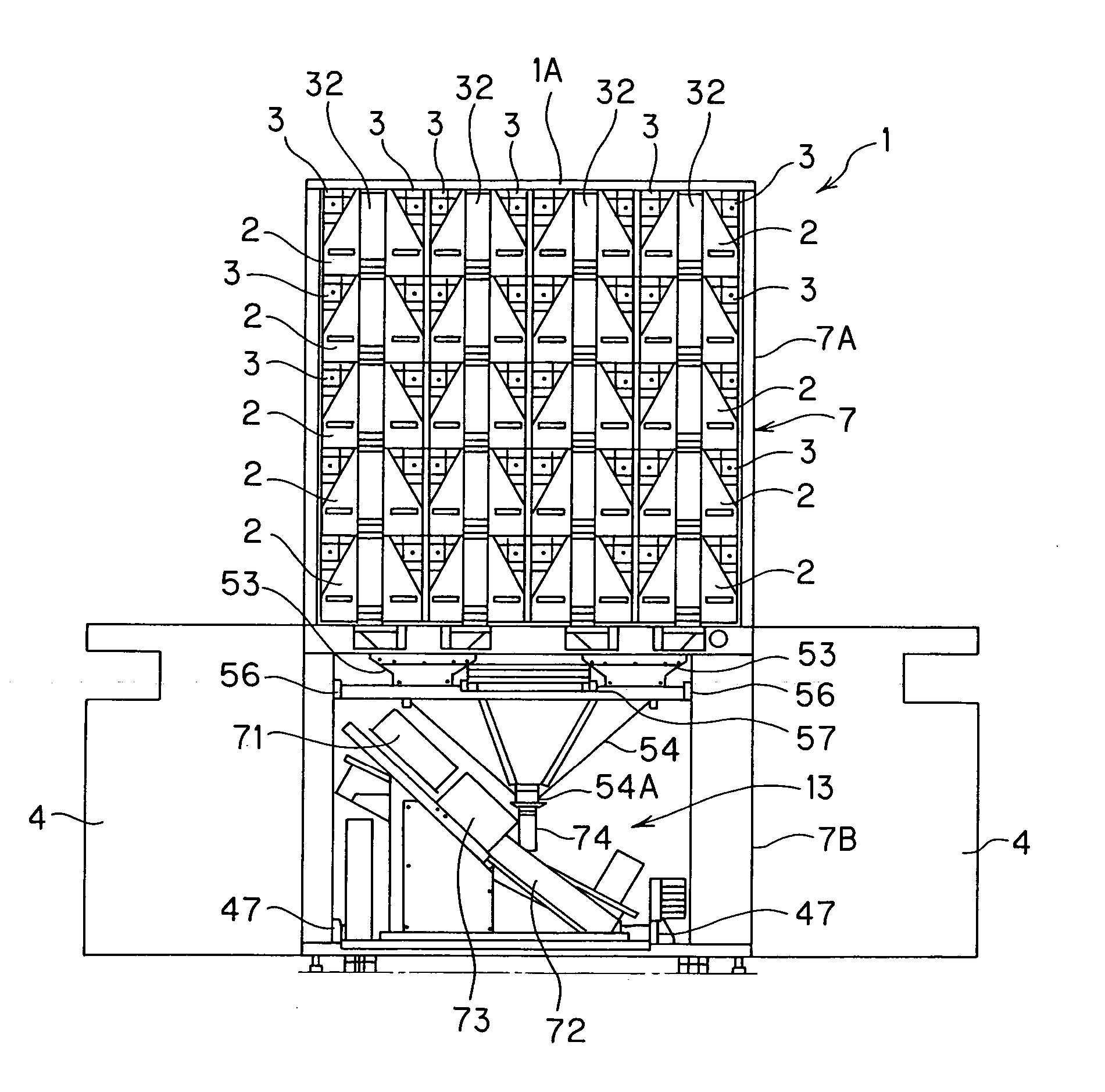
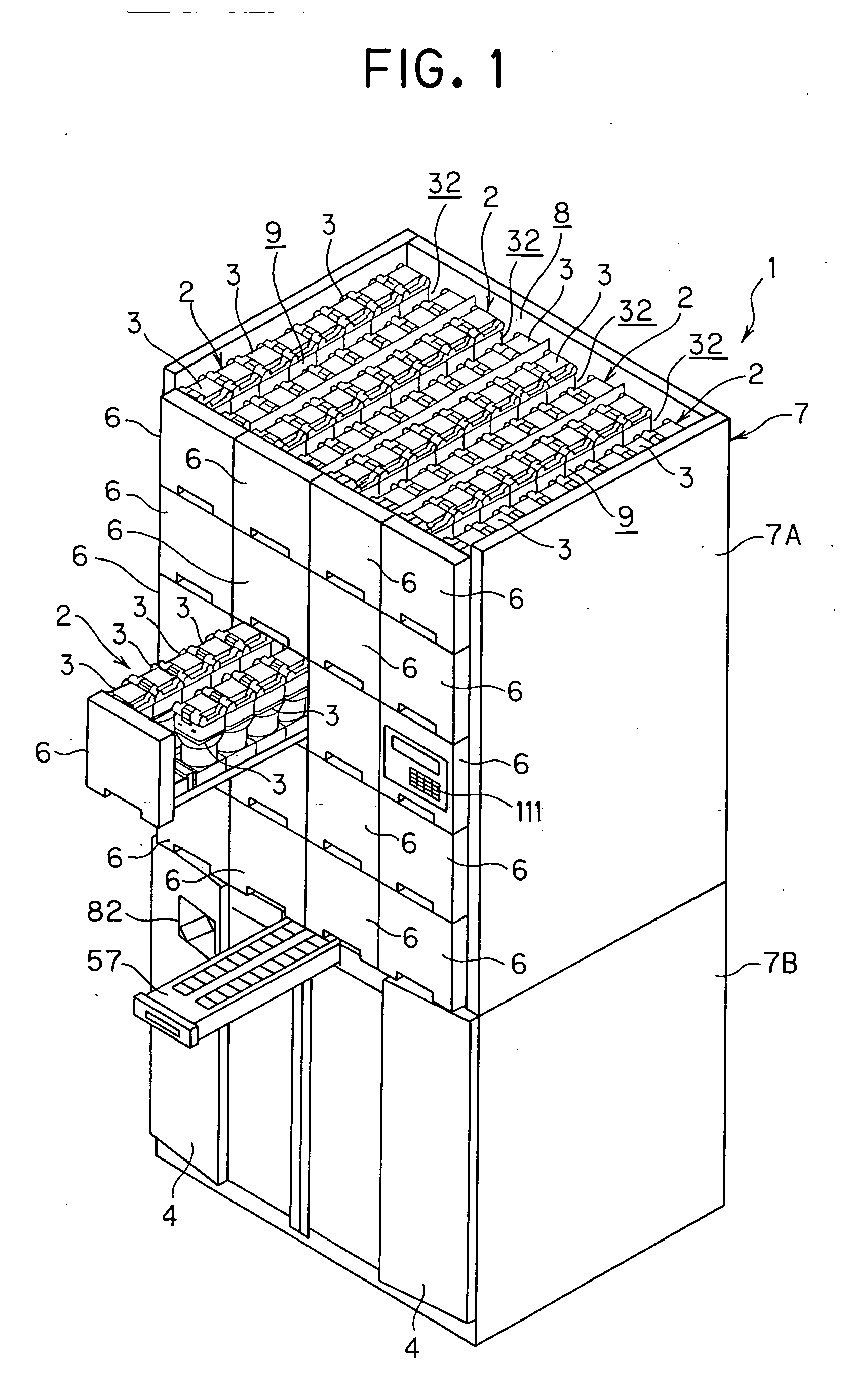
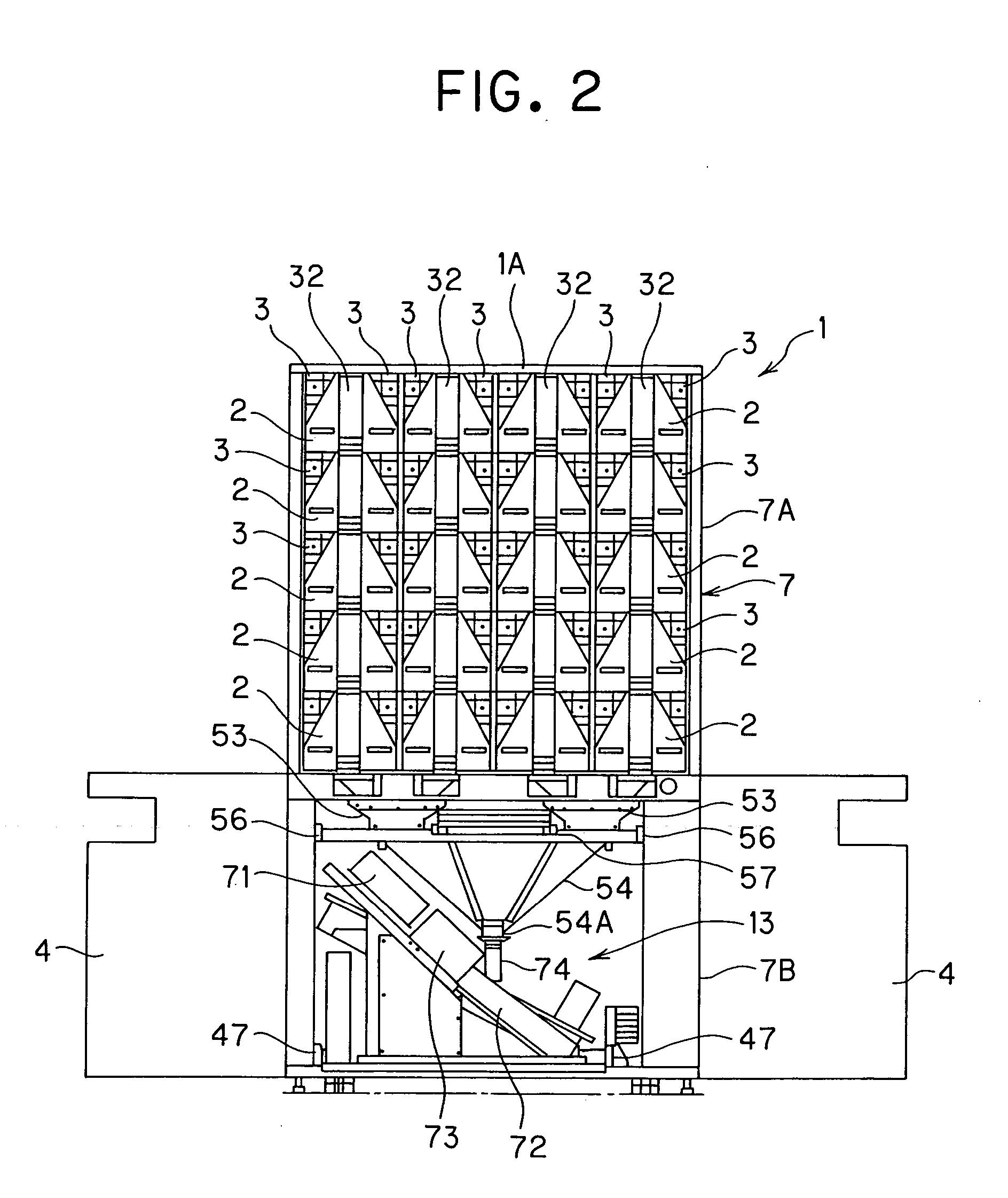
[0044] Embodiments of the present invention will be described in detail with reference to the drawings. FIG. 1 is a perspective view of a medicine supply apparatus 1 (excluding a top board 1A) according to an embodiment of the present invention, FIG. 2 is a front view of the medicine supply apparatus 1 under a state that a cover panel 6 of each drawer 2 is detached and lower panels 4 are opened, FIG. 3 is a longitudinally-sectional side view of the medicine supply apparatus 1, FIG. 4 is another front view of the medicine supply apparatus 1, FIG. 5 is a side view of the medicine supply apparatus 1, FIG. 6 is a plan view showing the medicine supply apparatus 1, FIG. 7 is a perspective view of a drawer 2, FIG. 8 is a perspective view of the drawer 2 under the state that an accommodating container 51 of the tablet cases 3 is detached, FIG. 9 is a perspective view showing the accommodating container 51 of the tablet cases 3, FIG. 10 is an exploded perspective view showing a driving base ...


PUM

PropertyMeasurementUnit
voltageaaaaaaaaaa
timeaaaaaaaaaa
sizeaaaaaaaaaa

Abstract

In a medicine supply apparatus having a plurality of tablet cases equipped in a case accommodating portion of a main body, each tablet case containing medicines, chutes into which medicines discharged from the respective table cases fall, a hopper equipped in correspondence with the lower portions of the chutes, and a charging apparatus for charging a medicine accommodating container with medicines caught by the hopper, a plurality of drawers are equipped in the case accommodating portion, the tablet cases are detachably mounted on each drawer, and each drawer is equipped so as to be freely drawn out from the case accommodating portion.

Description

TECHNICAL FIELD [0001] The present invention relates to a medicine supply apparatus for supplying a container (bottle, bag or the like) with medicines accommodated in a tablet case by a prescribed number indicated by a medical prescription in a hospital, a pharmacy or the like. BACKGROUND ART [0002] In a hospital or pharmacy, it has been general that medicines prescribed by a doctor are supplied to a patient by using a medicine supply apparatus disclosed in JP-UM-B-57-5282 (B65B1 / 30) (it is referred to as a tablet packaging machine in this publication), for example. According to this system, medicines (tablets, capsules or the like) whose number is indicated in a medical prescription are discharged from the inside of a tablet case one by one by using a discharge drum (referred to as an array board in the above publication), passed through a chute and then collected in a hopper. Thereafter, the medicines thus collected are packaged with packaging paper or put in a bottle. [0003] An e...

Claims


Application Information

Patent Timeline
07 Jul 2005
Publication
US20050145644A1
IPC
A61J7/00; B65B5/10; B65B9/06; B65B35/00; B65B39/00; B65B59/04; B65B1/30; G07F11/62
CPC
B65B5/103; B65B35/00; G07F17/0092; G07F11/62; B65B59/04; B65B1/30; B65B9/06; B65B39/00
Inventors
MORI, TAKASHI; TAKAHASHI, HIDEYUKI