Online general vehicle wheel deburring device

a vehicle wheel and deburring technology, applied in metal-working machines, manufacturing tools, polishing machines, etc., can solve the problems of poor deburring effect of vehicle wheels, and achieve the effects of high generality, advanced technology, and high degree of automation

a vehicle wheel and deburring technology, applied in metal-working machines, manufacturing tools, polishing machines, etc., can solve the problems of poor deburring effect of vehicle wheels, and achieve the effects of high generality, advanced technology, and high degree of automation

US20170182616A1Active Publication Date: 2017-06-29CITIC DICASTAL

Image

  • Online general vehicle wheel deburring device
  • Online general vehicle wheel deburring device
  • Online general vehicle wheel deburring device

Examples


Embodiment Construction

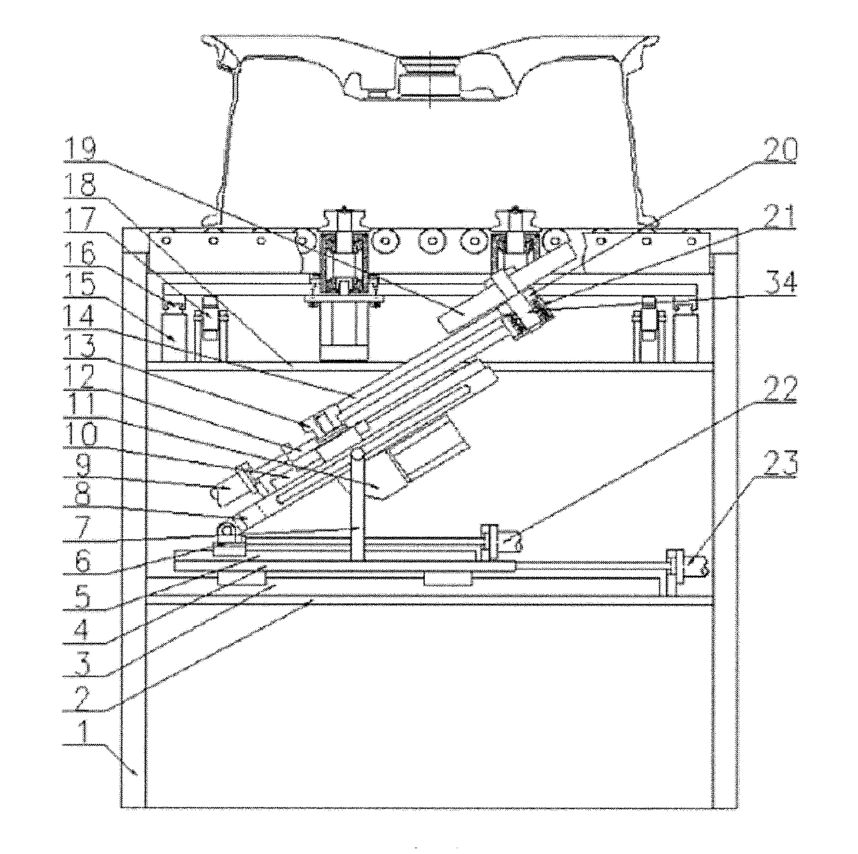
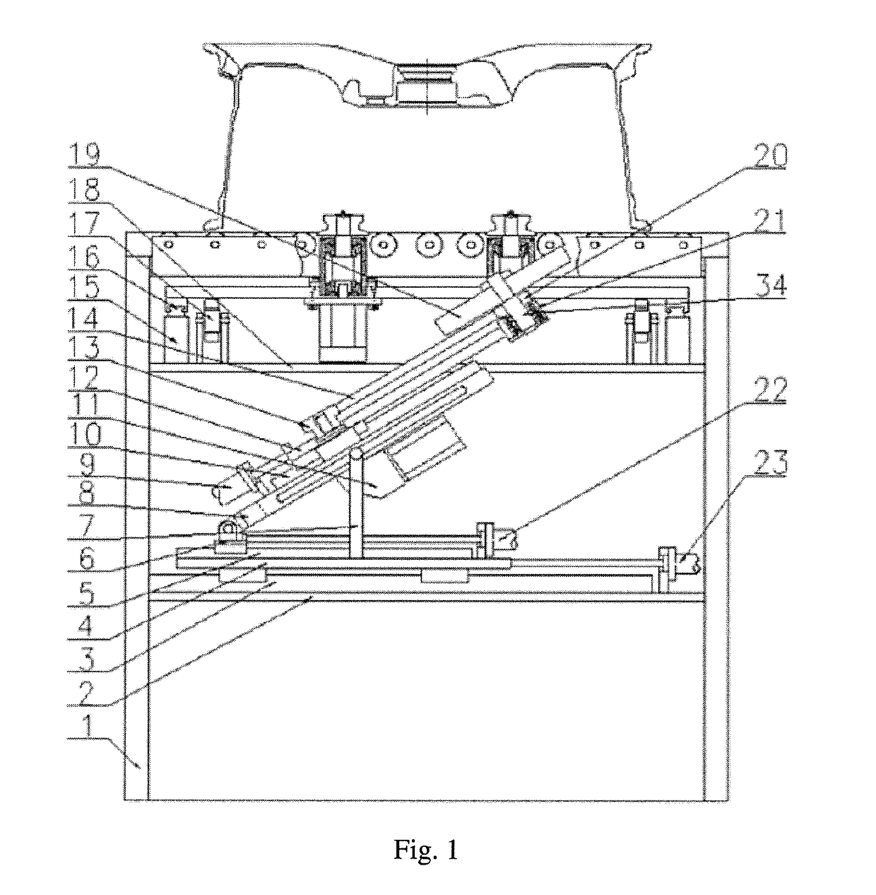
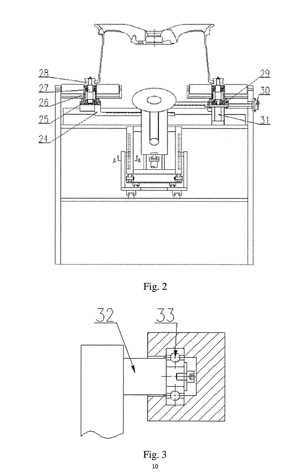
[0013]In the following, the details and working conditions of a specific device provided by the present invention are described in detail in combination with figures.

[0014]The device comprises a frame 1, a bottom plate 2, a guide rail I 3, a sliding plate 4, a guide rail II 5, a sliding block 6, a supporting rod 7, a roll-over stand 8, a lifting cylinder 9, a guide rail III 10, a servo motor 11, a lifting plate 12, a belt pulley I 13, a synchronous belt 14, a supporting block 15, a guide rail IV 16, gears 17, a supporting plate 18, a brush 19, a belt pulley II 20, a bearing base I 21, a servo electric cylinder I 22, a servo electric cylinder II 23, gear racks 24, a left sliding table 25, a bearing base II 26, a shaft I 27, V-shaped rollers 28, a right sliding table 29, a clamping cylinder 30, a driving motor 31, a pin shaft 32, rolling bearings 33 and a shaft II 34, wherein the bottom plate 2 is fixed below the frame 1; the sliding plate 4 is mounted above the bottom plate 2 by the ...


PUM


Abstract

The present invention discloses an online general vehicle wheel deburring device comprising a frame, an air cylinder, a guide rail, a servo electric cylinder and the like, wherein a vehicle wheel on a roller way is initially positioned by a sensor, a clamping cylinder clamps the vehicle wheel by using four V-shaped rollers by virtue of gears, gear racks and the guide rails IV, and the vehicle wheel is rotated in a clamping state under the action of a driving motor; the angle of a brush can be randomly adjusted by the servo electric cylinder I by virtue of the guide rail the angle of the brush can be randomly adjusted by the servo electric cylinder II by virtue of the guide rail I; the lifting height of the brush can be adjusted by the lift cylinder by virtue of the guide rail III.

Description

CROSS-REFERENCE TO RELATED APPLICATIONS[0001]This application claims priority to Chinese Patent Application No. 201511006526.1, filed on Dec. 29, 2015, which is hereby incorporated by reference in its entirety.TECHNICAL FIELD[0002]The present invention relates to a deburring device, in particular to an online deburring device for a back cavity of a vehicle wheel.BACKGROUND ART[0003]In the production course of aluminum alloy vehicle wheels, removing burrs on a back cavity after machining is an important procedure. In the present common method, deburring is performed on the back cavity with a large disc brush on special equipment; when the manner is adopted, the burr removing effect is poor for vehicle wheels with complex modeling, and only manual grinding is performed to meet requirements. At present, a deburring device with high automation degree, which not only can adapt to deburring requirements for any complex modeling but also can perform focused treatment on a certain specific ...

Claims


Application Information

Patent Timeline
29 Jun 2017
Publication
US20170182616A1
IPC
B24B9/04; B24B29/04; B24B29/00
CPC
B24B9/04; B24B29/04; B24B29/005
Inventors
XUE, BOWEN; GUO, JIANDONG