

Knee brace hinges with adaptive motion
- Summary
- Abstract
- Description
- Claims
- Application Information
AI Technical Summary
Benefits of technology
Problems solved by technology
Method used
Image

Examples
Embodiment Construction
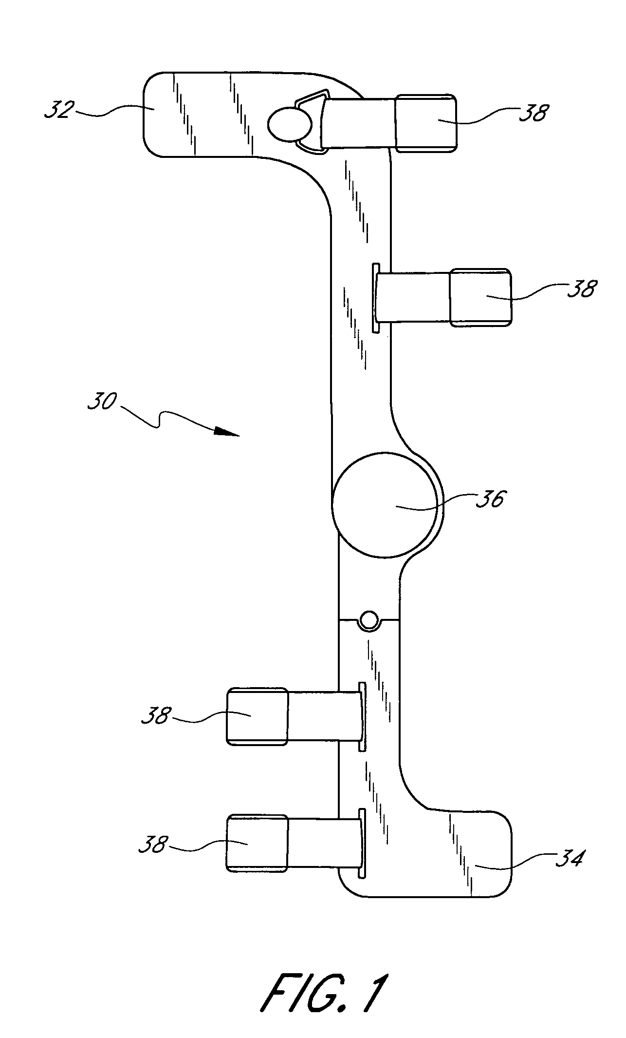
,” one will understand how the features of the preferred embodiments provide advantages, which include the ability to track natural knee motion so as to avoid applying undesired forces to the knee, while at the same time restraining the knee against harmful motions.
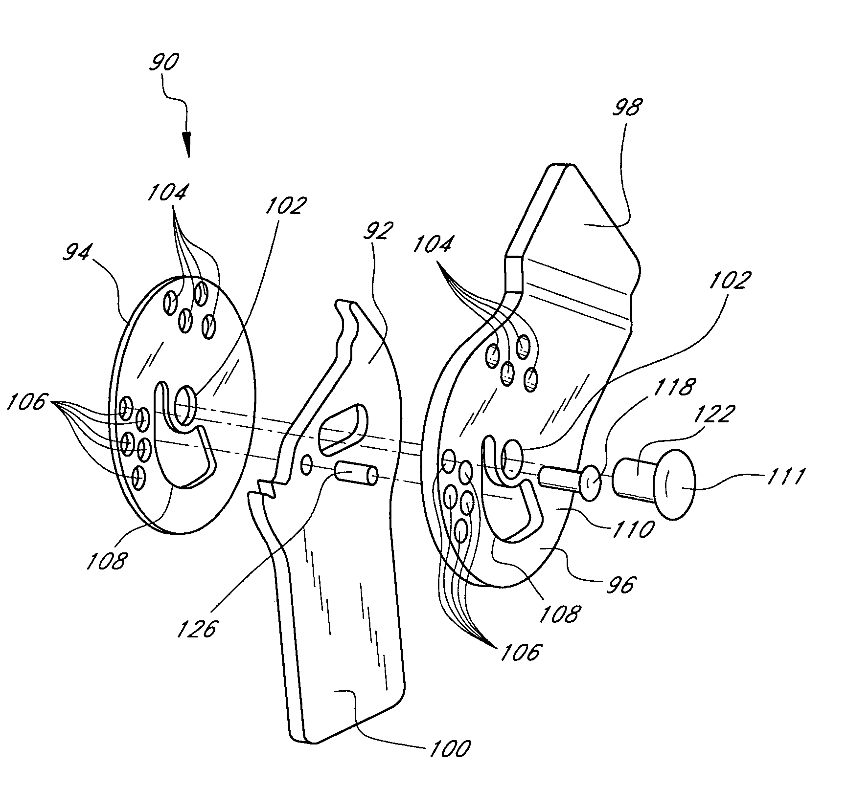
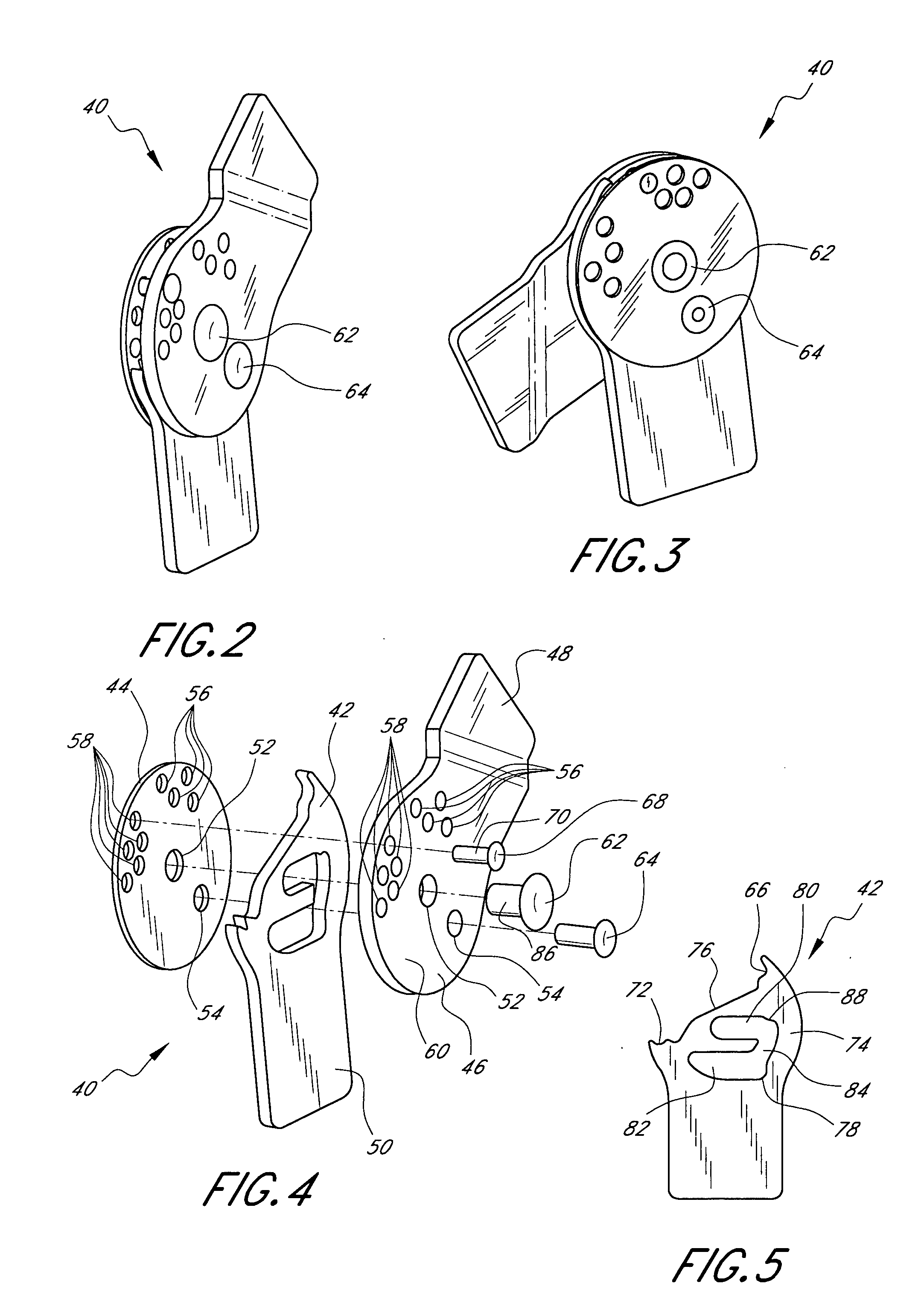
[0011] One embodiment of the present knee brace hinges comprises at least a first hinge plate and a cam plate. The hinge plate and the cam plate are secured to one another such that in a first range of motion the hinge plate is pivotable with respect to the cam plate but not translatable with respect thereto, and in a second range of motion the hinge plate is pivotable and translatable with respect to the cam plate.
[0012] Another embodiment of the present knee brace hinges comprises at least a first hinge plate including a pivot aperture and a guide aperture, a cam plate including a cam slot, the cam plate being secured to the hinge plate, a pivot member extending through the pivot aperture and the cam slot, and a guide ...
PUM
 Abstract
Description
Claims
Application Information