Thrust device

a thrust device and thrust plate technology, applied in the direction of power-driven steering, steering gears, portable lifting, etc., can solve the problems of lack of play between the pressure piece and the spring element arrangement, and the development of noise by the thrust device cannot be ruled out, so as to achieve low noise operation, simple construction, and narrow range

Inactive Publication Date: 2005-07-14
ZF LENKSYST
View PDF6 Cites 12 Cited by
  • Summary
  • Abstract
  • Description
  • Claims
  • Application Information

AI Technical Summary

Benefits of technology

[0006] The invention is based on the object of providing a thrust device for mechanism members which makes low-noise operation of the mechanism members possible with a simple construction and a thrust force which can be varied in a narrow range.

Problems solved by technology

During operation of the gear mechanism, the development of noise by the thrust device cannot be ruled out, as the pressure piece comes into contact with the mechanism casing when the drive shaft is pivoted to its maximum, structurally predefined extent.
In addition, an adjusting element is arranged in series with the spring element and produces a lack of play in the arrangement of the pressure piece and the spring element.

Method used


Image

  • Thrust device
  • Thrust device
  • Thrust device

Examples


Embodiment Construction

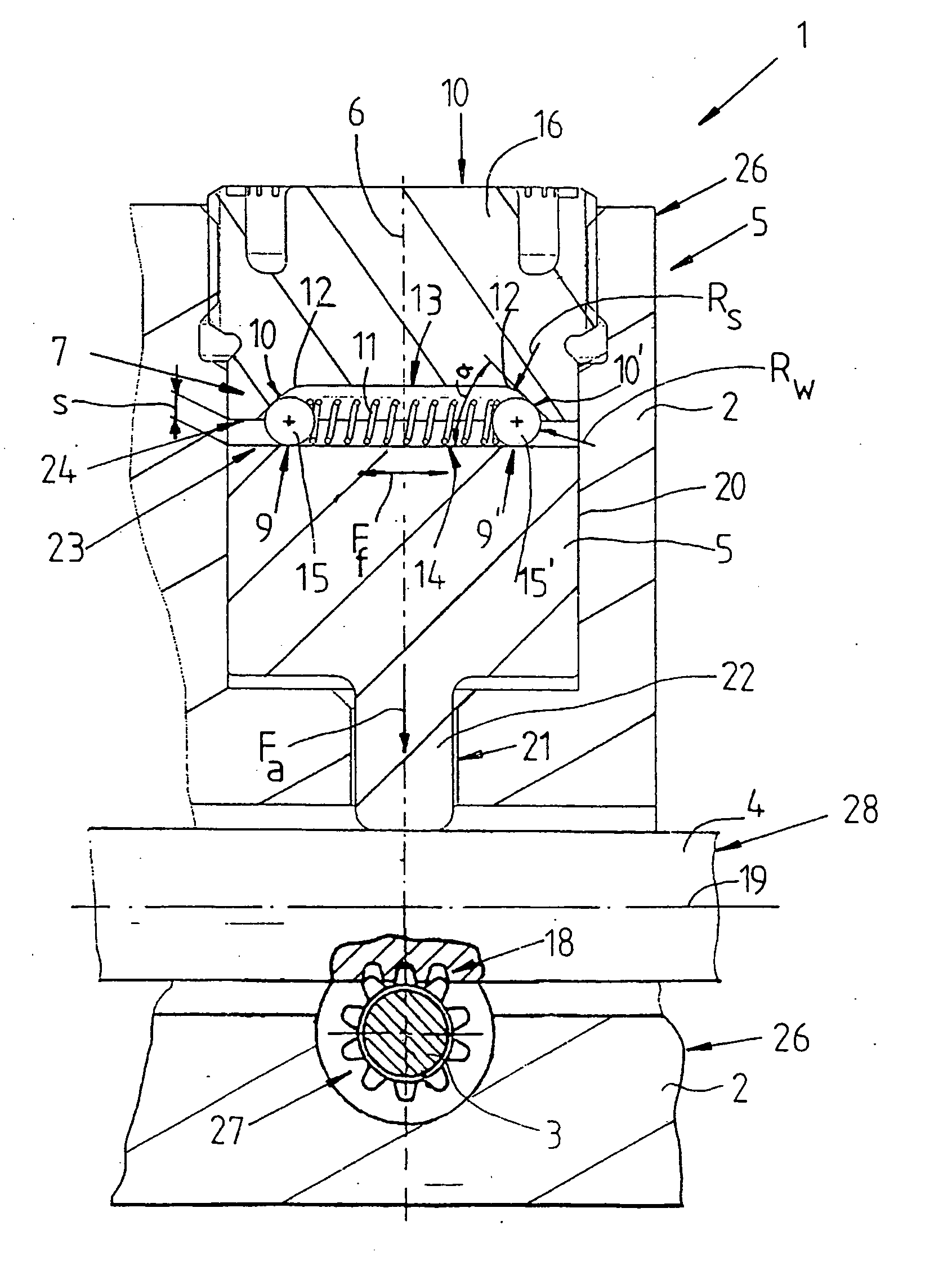
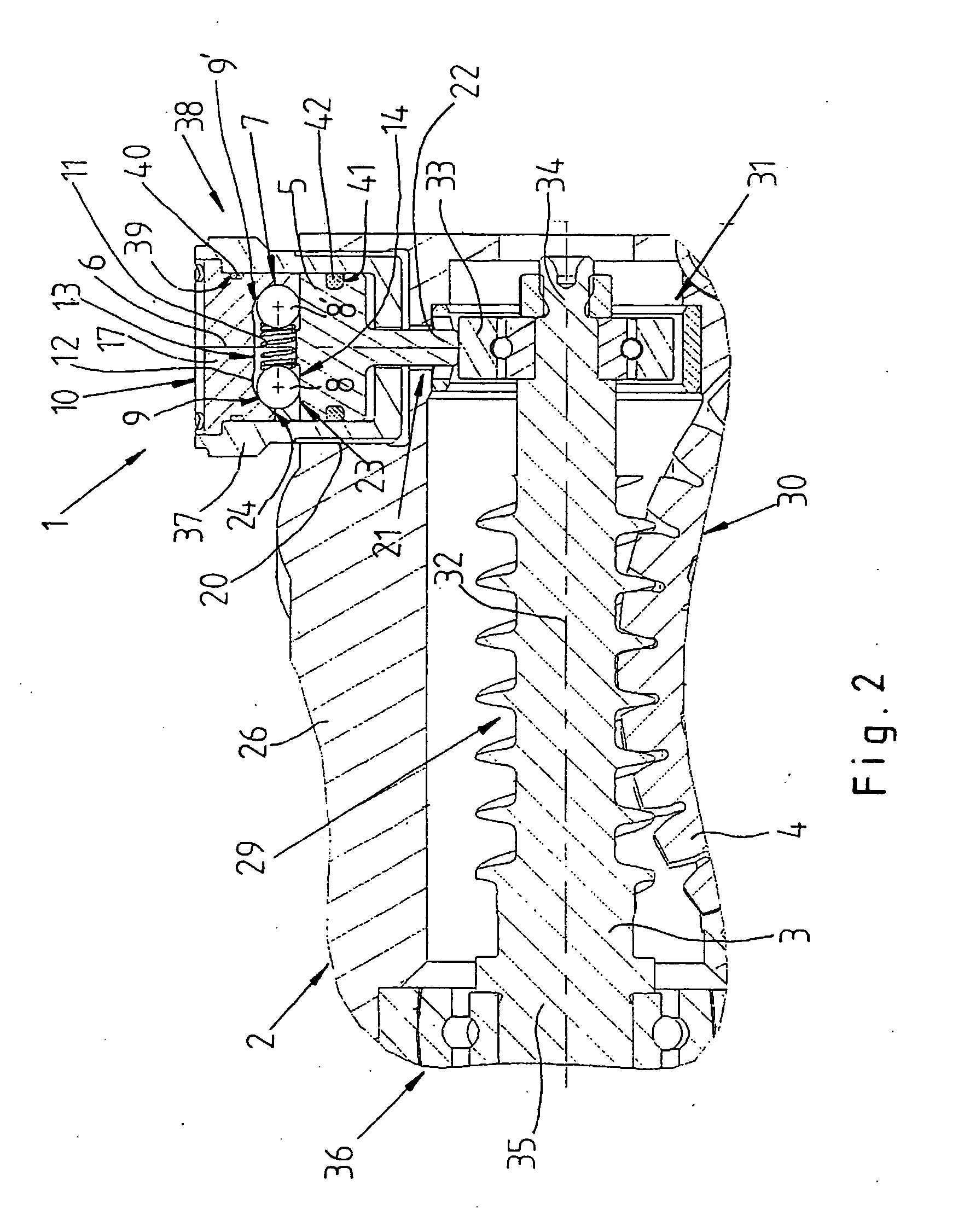
[0022]FIG. 1 partially shows a cross section of a steering system which is configured as a rack and pinion steering system for a motor vehicle. Here, a frame 2 which is configured as a mechanism casing 26 is shown in the axial direction with respect to a rack 28 in the region of a thrust device 1. The rack 28 bears toothing 18 which extends over the rack 28 in the axial direction and is in engagement with a pinion 27 which is connected fixedly to the end of a steering shaft so as to rotate with said steering shaft.

[0023] The pinion 27 is mounted rotatably in the mechanism casing 26 in a manner which is not shown in greater detail and forms a first mechanism member 3. The rack 28 is displaced in the axial direction as a function of a rotation of the pinion 27 at a steering handle on the steering shaft. The rack 28 forms a second mechanism member 4 and is connected to steerable wheels of the motor vehicle using steering tie rods and wheel steering levers.

[0024] The toothing 18 of th...


PUM


Abstract

A thrust device, in particular for a roller cam mechanism in a steering system, includes a first mechanism member which is held on a frame in engagement with a second mechanism member. The thrust device comprises a pressure piece which is mounted on the frame so as to be displaceable along an axis and is acted on by a spring element for pressing the first and second mechanism members against one another. In order to construct the thrust device for compensating for wear and thermal expansion of the engagement of the mechanism members and to configure it to be inexpensive and quiet during operation, there is provision for the spring element to be formed from rolling bodies which are spring loaded approximately transversely with respect to the axis of the pressure piece, the rolling bodies being supported on oblique surfaces between the pressure piece and a frame part which is configured as a setting screw or cover. The pressure piece can additionally be spring loaded axially by a compression spring.

Description

BACKGROUND OF THE INVENTION [0001] The invention relates to a thrust device, in particular 5 for a roller cam mechanism in a steering system. [0002] DE 100 51 306 A1 describes a gear mechanism, in particular for a vehicle steering system, having a pinion which is configured as a first mechanism member and is connected fixedly to a drive shaft of a servomotor so as to rotate with it. The pinion is in engagement with a second mechanism member which is configured as a gear wheel. The drive shaft is held pivotably in a locating bearing and a floating bearing. The floating bearing is held radially displaceably in a frame which is configured as a mechanism casing. The floating bearing is pressed onto the gear wheel by a spring element in the radial direction via a supporting ring which serves as a pressure piece. The supporting ring is held radially displaceably in a slot in the mechanism casing and is secured against rotation via the spring element. [0003] During operation of the gear me...

Claims


Application Information

Patent Timeline
Patent Type & Authority Applications(United States)
IPC IPC(8): B62D3/12B62D5/04F16H55/24F16H55/28
CPCB62D3/123B62D5/0409F16H2057/0213F16H55/24F16H55/283F16H25/183
Inventor NGUYEN, DANH LUANGRAU, MARCOHETZEL, OLIVERBERROTH, ERICH
Owner ZF LENKSYST
Why Eureka
Try Eureka