Driving circuit of liquid crystal display

Inactive Publication Date: 2005-08-04
BOE HYDIS TECH
View PDF5 Cites 16 Cited by
  • Summary
  • Abstract
  • Description
  • Claims
  • Application Information

AI Technical Summary

Benefits of technology

[0013] Accordingly, the present invention has been made to solve the above-mentioned problems occurring in the prior art, and it is an object of the present invention to provide a driving circuit of a liquid crystal display device capable of efficiently using a wiring connected between a timing controller and each driver IC by transmitting data using a protocol.
[0014] Another object of the present invention is to provide a driving circuit of a liquid crystal display device allowing for a minimized number of wiring connected between a timing controller and each driver IC by transmitting data using a protocol.

Problems solved by technology

In general, although a CRT (cathode ray tube), which is a kind of display device, is mainly used in monitors of televisions, various measurement apparatuses, and information terminals, a CRT has a heavy weight and a big size, so the CRT is not adaptable for electronic appliances having a small size and a light weight.
However, a driving circuit of the conventional liquid crystal display device has a problem, as follows.

Method used


Image

  • Driving circuit of liquid crystal display
  • Driving circuit of liquid crystal display
  • Driving circuit of liquid crystal display

Examples


Embodiment Construction

[0033] Hereinafter, preferred embodiments of the present invention will be explained with reference to the accompanying drawings.

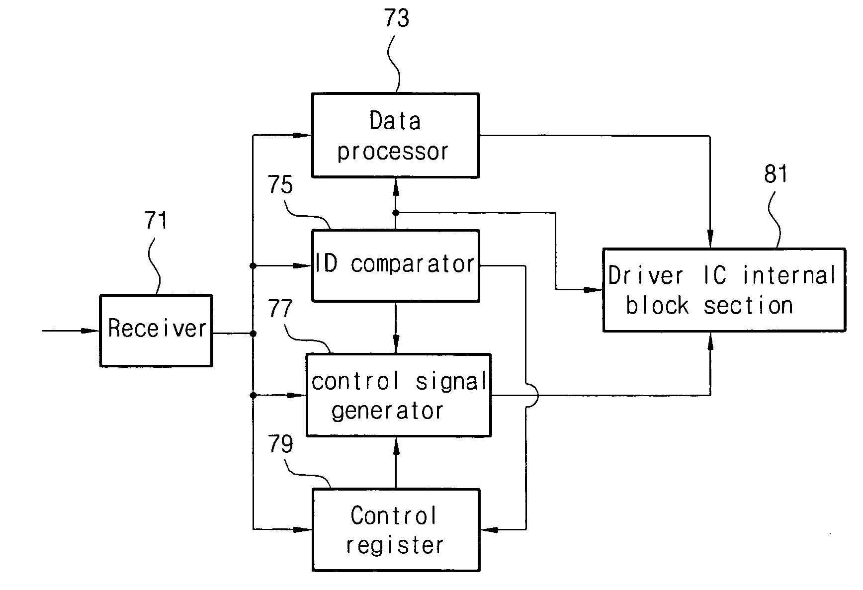
[0034]FIG. 4 is a block view showing a structure of a driving circuit of a liquid crystal display device according to the present invention. Referring to FIG. 4, the driving circuit of the present invention includes a timing controller 31 and a driver IC 33. A clock wiring 35 and a data and control signal bus 37 are positioned between the timing controller 31 and the driver IC 33.

[0035] According to the present invention, a bus is more effectively used through reducing the number of wirings by transmitting control signals to each driver ICs by way of the data and control signal bus 37 at a blank region in which data is not inputted. Also, only the data and control signal bus 37 for transmitting data and various control signals and the clock wiring 35 for transmitting a clock signal are positioned between the timing controller and the driver IC, so data a...


PUM


Abstract

Disclosed is a liquid crystal display device having a wiring connected between a timing controller and each driver IC. The liquid crystal display includes gate driver ICs applying gate voltage to the liquid crystal panel, source driver ICs applying source voltage to the liquid crystal panel, a timing controller applying various control signals and data signals to each of the gate and source driver ICs, a data and control signal bus connected between the gate driver ICs and the timing controller and between the source driver ICs and the timing controller, and a clock wiring connected between the gate driver ICs and the timing controller and between the source driver ICs and the timing controller gate in order to transmit a clock signal outputted from the timing controller to each driver IC.

Description

BACKGROUND OF THE INVENTION [0001] 1. Field of the Invention [0002] The present invention relates to a liquid crystal display device, and more particularly to a driving circuit of a liquid crystal display device allowing for a reducing the number of wirings, and improving usage efficiency of a bus by transmitting various data and control signals from a timing controller to each driver IC using a protocol. [0003] 2. Description of the Prior Art [0004] In general, although a CRT (cathode ray tube), which is a kind of display device, is mainly used in monitors of televisions, various measurement apparatuses, and information terminals, a CRT has a heavy weight and a big size, so the CRT is not adaptable for electronic appliances having a small size and a light weight. [0005] Accordingly, liquid crystal display devices having a slimmer and compact size with a light weight have been actively developed in order to substitute for CRTs. Recently, such liquid crystal display devices have been...

Claims


Application Information

Patent Timeline
IPC IPC(8): G02F1/13G02F1/133G09G3/20G09G3/36G09G5/00
CPCG09G5/006G02F1/13452G09G3/36
InventorCHUNG, KYUNG HOON
OwnerBOE HYDIS TECH