
Wireless communications apparatus, and routing control and packet transmission technique in wireless network

Inactive Publication Date: 2005-10-27
NTT DOCOMO INC
View PDF16 Cites 29 Cited by
  • Summary
  • Abstract
  • Description
  • Claims
  • Application Information

AI Technical Summary

Benefits of technology

[0010] Therefore, it is an object of the present invention to solve the problems in the conventional techniques and to provide a routing control and packet transmission technique for a wireless network that can achieve both workload distribution among nodes and efficient use of radio resources.
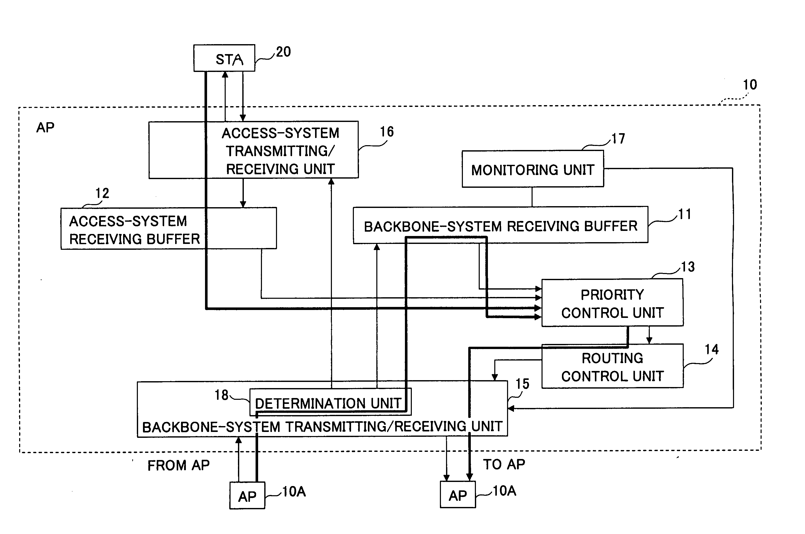
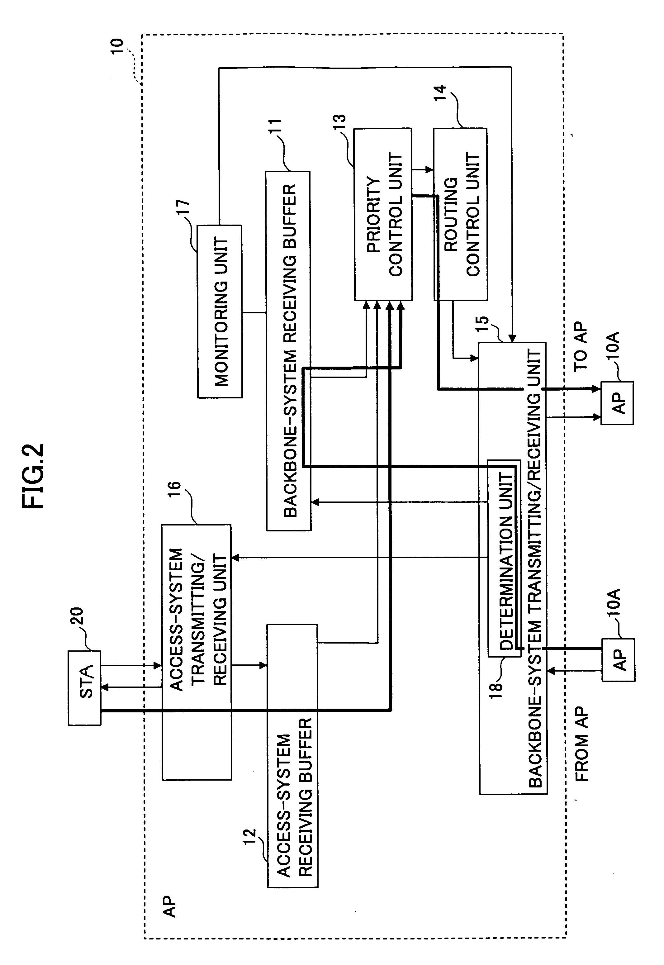
[0013] Independent of or in combination with the calculation of the node cost, a wireless communications apparatus (AP) is configured to have a backbone-system buffer for temporarily storing packets received from other nodes (or access points) and an access-system buffer for temporarily storing packets received from user terminals (STA) located under this wireless communications apparatus (AP) separately. Data transmission from these two buffers is scheduled based on a prescribed order of priority so as to reduce delay occurring at a node (wireless communications apparatus or access point) on which traffic is likely to converge.
[0016] By determining the transmission route based on both the link cost representing the wireless condition between adjacent wireless communications apparatuses and the node cost representing the traffic at the node, concentration of workload on a specific node can be avoided, while efficiently using the radio resources. Consequently, wireless transmission can be performed more efficiently.
[0017] Preferably, the routing control information processing unit is configured to exchange the cost information with the adjacent wireless communications apparatus, and upon receiving arbitrary cost information, to produce new cost information by adding the node cost of this wireless communications apparatus and the link cost from the adjacent wireless communications apparatus and transmit the new cost information to the next hop.
[0021] By storing information items in two types of buffers depending on where the information items are received from, and by controlling the transmission order of the information items, the packets can be relayed to the next hop without causing a significant delay even at a node on which traffic is apt to converge.
[0023] With this arrangement, concentration of workload on a specific node can be avoided, and the overall network efficiency can be maintained high by setting a suitable transmission route avoiding a heavy-traffic node. Consequently, radio resources can be used efficiently.

Problems solved by technology

However, this method is not capable of calculating a link cost reflecting adaptive changes in communication rate in the wireless environment.
Consequently, the throughput of the entire network cannot be improved.
With the above-described conventional techniques, load distribution cannot be realized in the network.
Or, even if workload is dispersed, efficient use of radio resources cannot be realized.

Method used


Image

  • Wireless communications apparatus, and routing control and packet transmission technique in wireless network
  • Wireless communications apparatus, and routing control and packet transmission technique in wireless network
  • Wireless communications apparatus, and routing control and packet transmission technique in wireless network

Examples


Embodiment Construction

[0031] The present invention is described in detail below in conjunction with the attached drawings.

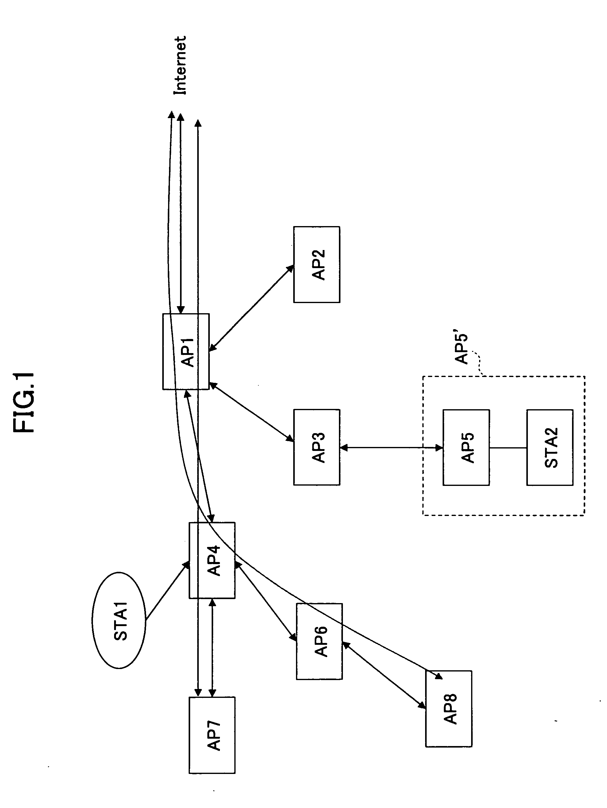
[0032]FIG. 1 is a schematic diagram illustrating an example of the network configuration of an ad-hoc network including multiple access points (wireless communications apparatus) AP1-AP8 that function as wireless base stations structuring a wireless backbone network. In addition, all or some of the access points AP1-AP8 function as wireless base stations controlling user terminals (STA) located under the associated access points. The access points AP1-AP8 are mutually connected via wireless links to form the wireless backbone network. A user terminal STA1 is located under the access point AP4, and another user terminal STA2 is connected to the access point AP5 via a cable in this example. The access point AP5 and the user terminal STA2 are integrated with each other to function as a single apparatus AP5′. Although not shown in FIG. 1, there may be some user terminals existing under e...


PUM


Abstract

A wireless communications apparatus used in a wireless communications network consisting of multiple wireless communications apparatuses mutually connected via wireless links includes (a) a buffer configured to temporarily store information received from an adjacent wireless communications apparatus or a user terminal located under the wireless communications apparatus; (b) a routing control information processing unit that estimates a node cost representing traffic at the wireless communications apparatus and a link cost representing a radio condition of the link to determine a transmission route based on cost information reflecting both the node cost and the link cost; and (c) a routing control unit that designates a next hop to which information accumulated in the buffer is to be transmitted according to the determined transmission route.

Description

FIELD OF THE INVENTION [0001] The present invention generally relates to an ad-hoc network consisting of multiple wireless nodes mutually connected via wireless links to structure a self-configured backbone network. More particularly, the present invention relate to routing control for determining the optimum route in the ad-hoc network by taking into account both the node cost and the link cost, and to packet transmission capable of reducing delay at nodes due to relay traffic. BACKGROUND OF THE INVENTION [0002] An ad-hoc network is a technique for self-configuring a communications network with multiple communications equipment sets that operates without a specific control station. [0003] A wireless ad-hoc network is adapted to realize the ad-hoc network technique using radio links or wireless links in the mobile environment, and many studies and much research have been conducted regarding to the wireless ad-hoc network. [0004] It is proposed to introduce the concept of a spanning ...

Claims


Application Information

Patent Timeline
IPC IPC(8): H04L12/28H04W4/24H04W28/14H04W40/00H04W74/08H04W84/12H04W88/08H04W92/00
CPCH04L45/124H04L45/125H04W40/12H04W4/24H04W28/14H04L45/127H04W84/18
Inventor TAKEDA, SHINJIYAGYU, KENGOFUJIWARA, ATSUSHI
Owner NTT DOCOMO INC
Learn More