Transmitter and wireless communication apparatus using the transmitter

a wireless communication and transmitter technology, applied in the direction of transmission monitoring, modulation, gain control, etc., can solve problems such as complex design, and achieve the effect of simple design, low noise, and improved suppression degree relative to noise of amplitude loop

Inactive Publication Date: 2005-08-11
GOOGLE TECH HLDG LLC +2
View PDF19 Cites 40 Cited by
  • Summary
  • Abstract
  • Description
  • Claims
  • Application Information

AI Technical Summary

Benefits of technology

[0021] In order to achieve a first object, the present invention described above provides a transmitter of polar-loop architecture having a phase control loop and an amplitude control loop, wherein, as loop filters for restricting a loop band of the amplitude control loop, a first filter with lag-lead characteristics (secondary or more filter including a capacitor and a resistor) and a second filter of a perfect integrator type (filter including only a capacitor) are employed, and wherein current-output type circuits are connected to respective front stages of the first filter and the second filter. By doing so, the first filter and the second filter can be configured by a passive filter comprising passive elements, so that an active filter including an operational amplifier is not required, which enables to simplify the design thereof.
[0022] In order to achieve the second object, the above-mentioned present invention provides a transmitter of polar-loop architecture having a phase control loop and an amplitude control loop, wherein, as loop filters for restricting a loop band of the amplitude control loop, a first filter with lag-lead characteristics and a second filter of a perfect integrator type are employed, and wherein the first filter is provided at a front stage thereof prior to the second filter. By doing so, a suppression degree relative to noise of the amplitude loop can be improved and thereby a transmitter with low noise can be realized.

Problems solved by technology

Therefore, there arises a problem that the design becomes complicated.

Method used


Image

  • Transmitter and wireless communication apparatus using the transmitter
  • Transmitter and wireless communication apparatus using the transmitter
  • Transmitter and wireless communication apparatus using the transmitter

Examples


first embodiment

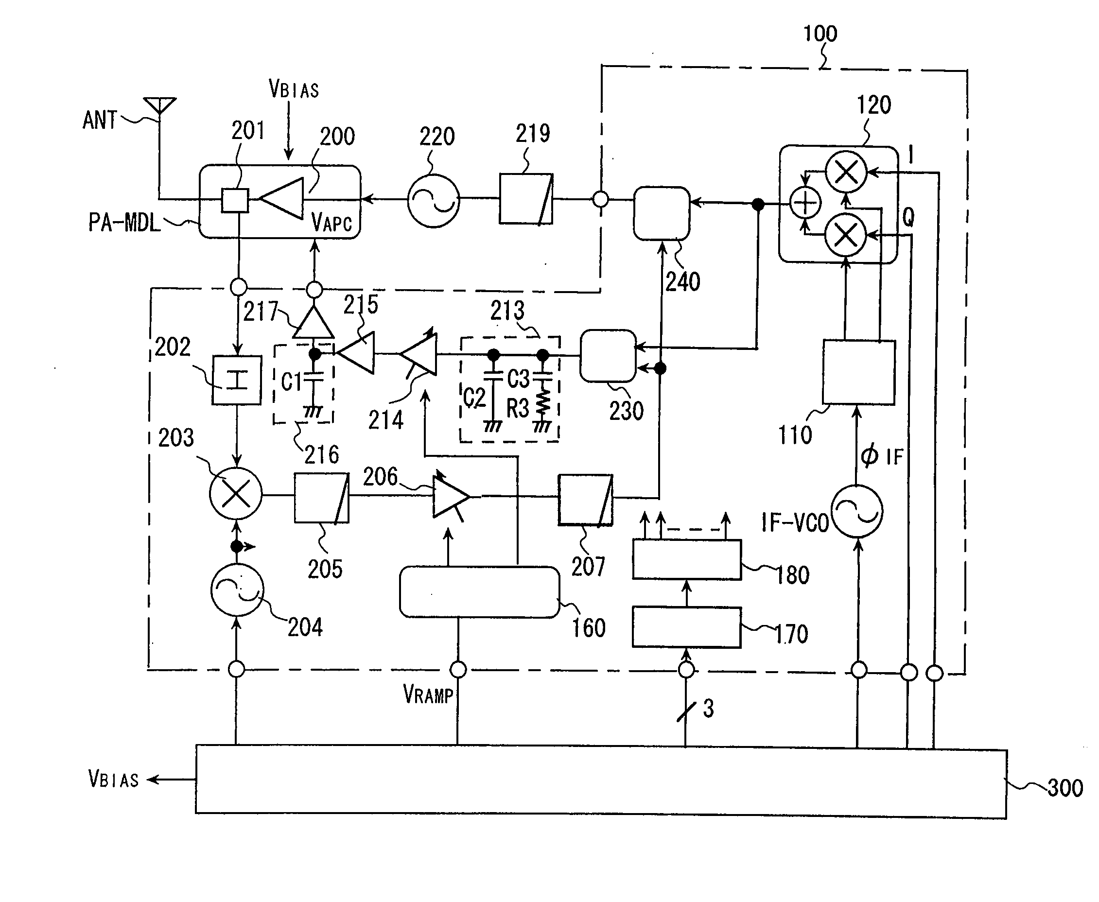
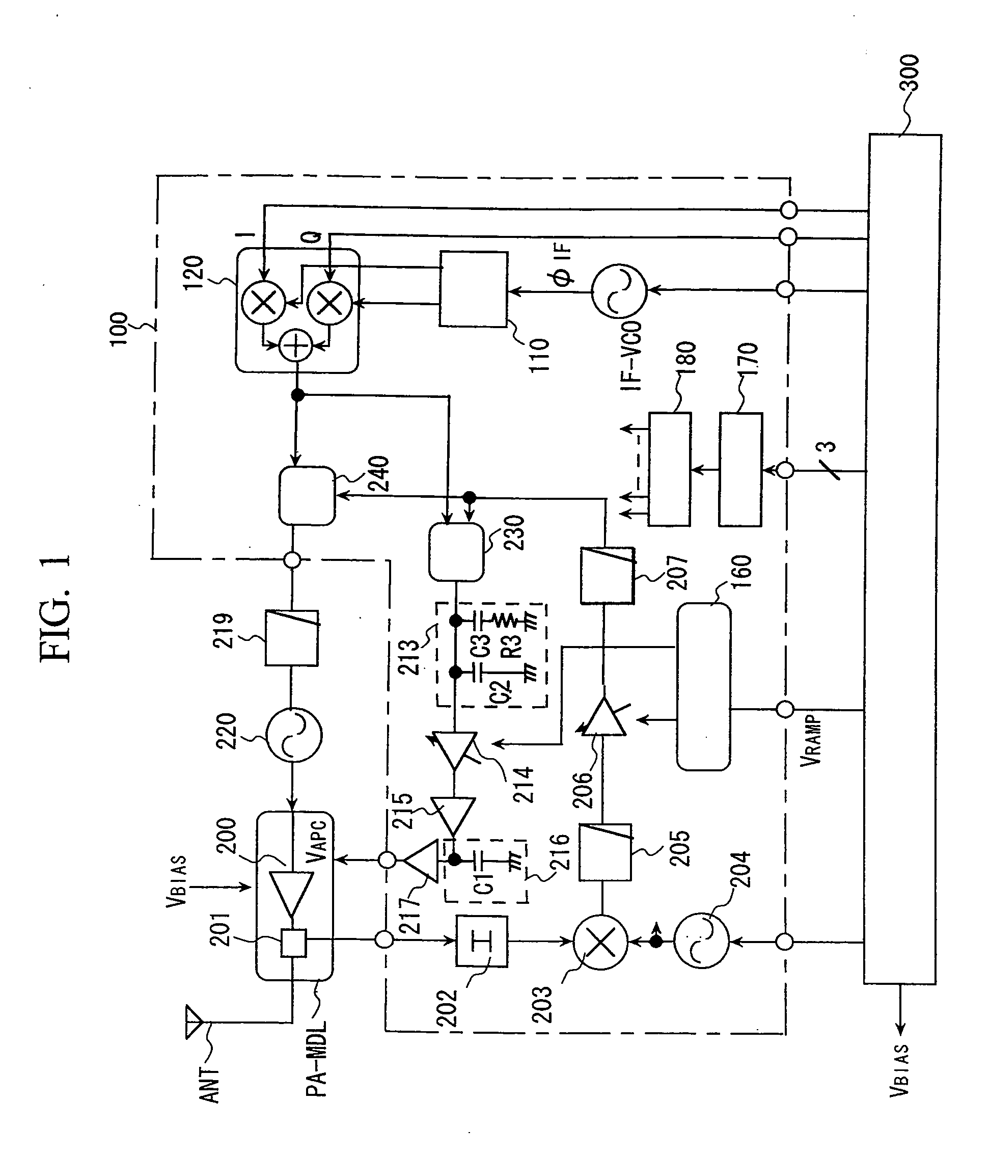
[0035]FIG. 1 is a configuration diagram showing a transmitter according to the present invention.

[0036] The transmitter according to the present embodiment employs a polar-loop architecture described in “BACKGROUND OF THE INVENTION”, and has a phase loop and an amplitude loop and is configured as a transmitter for EDGE.

[0037] In FIG. 1, numeral 100 denotes a high frequency IC for performing a phase modulation and an amplitude modulation; PA-MDL denotes a power module which includes a nonlinear power amplifier 200 (hereinafter, referred to as a power amplifier) for amplifying and outputting a transmission signal or includes output detecting means 201 such as a coupler or a signal branching device of the like for detecting a transmission output; numeral 300 denotes a base band circuit for generating I / Q signals (base band signals) on the basis of transmission data, or for generating a control signal of the high frequency IC 100 or a bias voltage VBIAS for the power amplifier 200 in t...

second embodiment

[0068] Next, the transmitter according to the present invention will be described.

[0069]FIG. 4 is a configuration diagram showing the second embodiment of the transmitter according to the present invention. The transmitter according to the present embodiment employs a configuration in which the limiters 208 and 210 commonly utilized in the amplitude loop and the phase loop in the first embodiment are used for the amplitude loop and in which limiters 300 and 301 are added for the phase loop, such that each loop has the limiters. According to the present embodiment, it is advantageous that the respective characteristics of the limiters can be optimized for each loop.

third embodiment

[0070] Next, the transmitter according to the present invention will be described.

[0071]FIG. 5 is a configuration diagram showing the third embodiment of the transmitter according to the present invention. In the second embodiment, the transmitter according to the present embodiment has a configuration in which second signal branching means 403 is inserted in the front stage of the power amplifier 200, that is, inserted between the transmission VCO 220 and the power amplifier 200; and a second attenuator 402 for attenuating the output of the signal branching means 403, a second mixer 400, and a filter 401 are provided; and the output of this filter 401 is fed back to the phase detector 218 via the limiter 300, so that the phase loop is configured separately from the amplitude loop. The local signal supplied to the second mixer 400 is in common used as the local signal to the mixer 203, and is supplied from the local VCO 204. The output signal of the mixer 400, whose undesired harmon...


PUM


Abstract

In a transmitter of polar-loop architecture having a phase control loop and an amplitude control loop, as loop filters for controlling a loop band of the amplitude control loop, a first filter with lag-lead characteristics (secondary or more filter including a capacitor and a resistor) and a second filter of a perfect integrator type (filter including only a capacitor) are employed, and current-output type circuits are connected to respective front stages of the first and second filters.

Description

BACKGROUND OF THE INVENTION [0001] The present invention relates to a technique for facilitating reduction in noise and a design of a loop filter relative to a transmitter which has a high frequency power amplifier and performs a control of an output power by a feedback control, and particularly to a technique effectively applied to a transmitter having a phase control loop and a technique effectively applied to an amplitude control loop for performing a phase modulation and an amplitude modulation and a wireless communication apparatus using this transmitter such as a mobile phone. [0002] In a mobile phone, needs of a high-speed data communication in addition to a speech communication have been increased in recent years. In GSM (Global System for Mobile communications) that is one of European Mobile Communications Standards, on the basis of a conventional system using a GMSK (Gaussian Minimum Shift Keying) modulation architecture, GPRS (General Packet Radio Service) for speeding up...

Claims


Application Information

Patent Timeline
Patent Type & Authority Applications(United States)
IPC IPC(8): H03G3/30H04B1/04H03F3/189H04L27/36
CPCH03G3/3042H04L27/361H04B2001/0433H04B1/0475H03F3/24H03F1/34
Inventor YAMAWAKI, TAIZOKAJIWARA, HISAYOSHITAKANO, RYOICHIWURM, PATRICK
Owner GOOGLE TECH HLDG LLC
Why Eureka
Try Eureka