Antenna alignment system and method

an antenna alignment and antenna technology, applied in the field of antennas, can solve the problems of increasing the cost of aligning the antenna, and achieve the effect of improving the antenna alignment system

Inactive Publication Date: 2005-09-15
10322156 CANADA INC
View PDF10 Cites 14 Cited by
  • Summary
  • Abstract
  • Description
  • Claims
  • Application Information

AI Technical Summary

Benefits of technology

[0006] It is therefore a general object of the present inventi

Problems solved by technology

While this procedure is relatively straightforward, it suffers from a number of significant disadvantages.
This is often expensive, especially if multiple measurements are to be made.
In addition, the p

Method used


Image

  • Antenna alignment system and method
  • Antenna alignment system and method
  • Antenna alignment system and method

Examples


Embodiment Construction

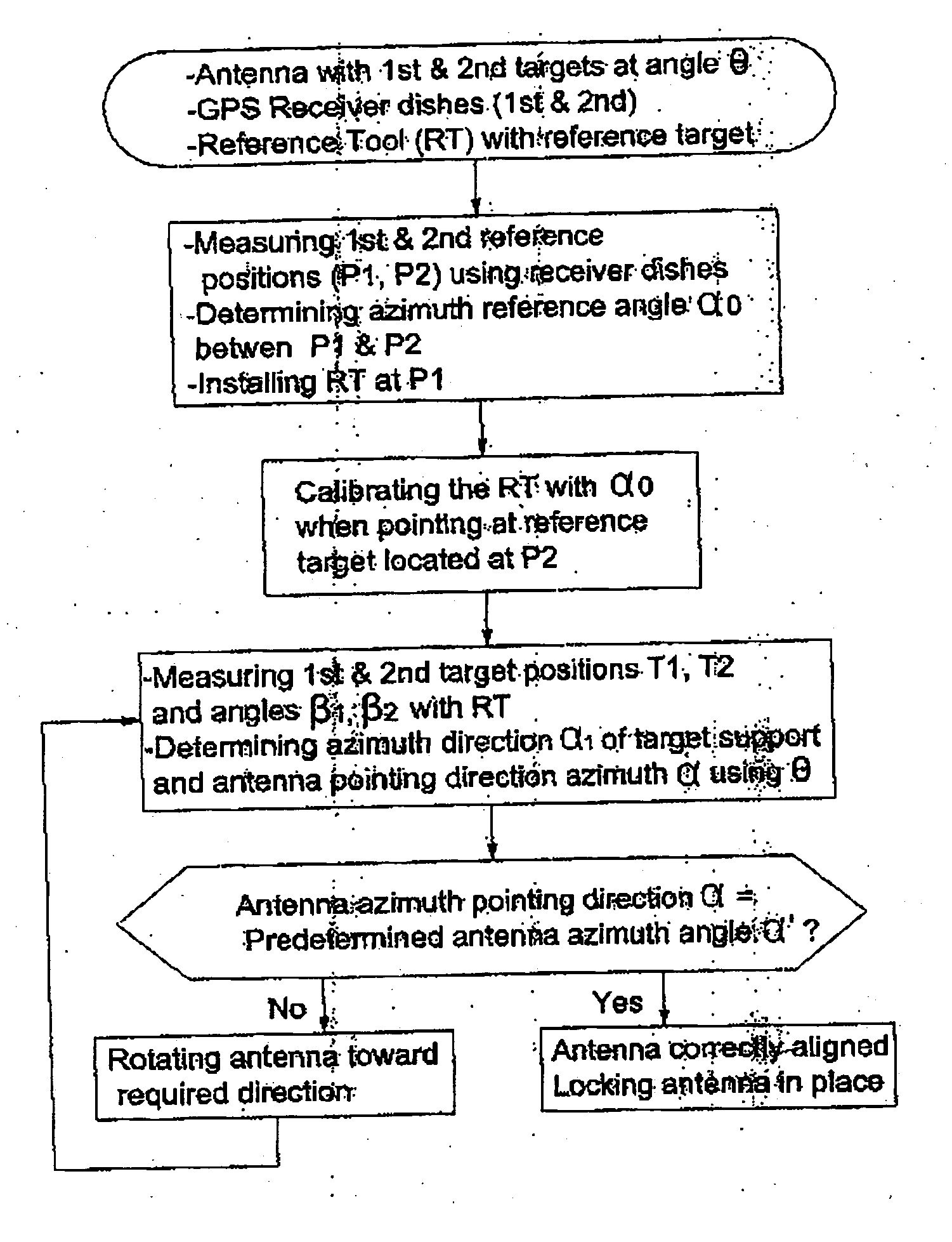
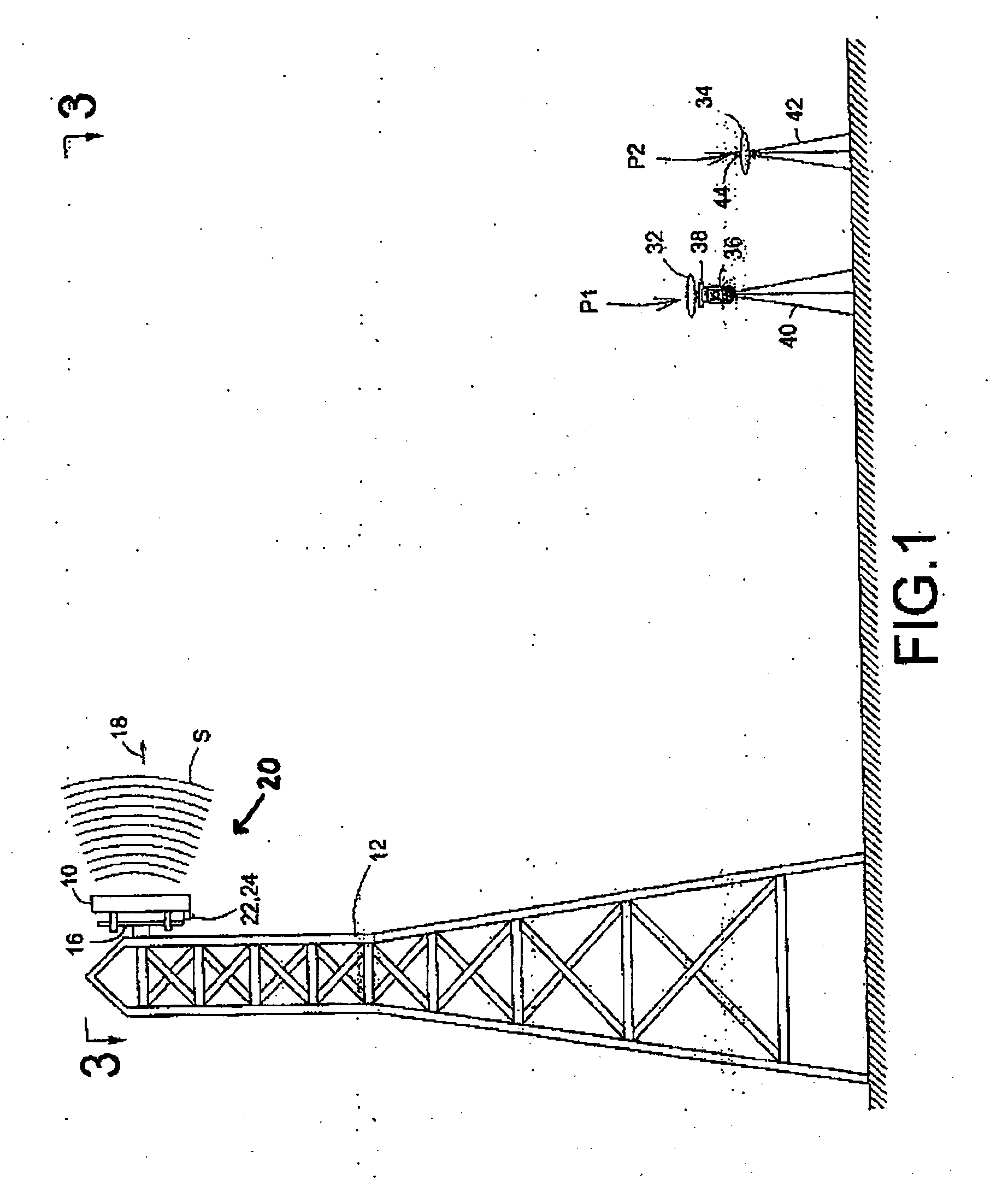
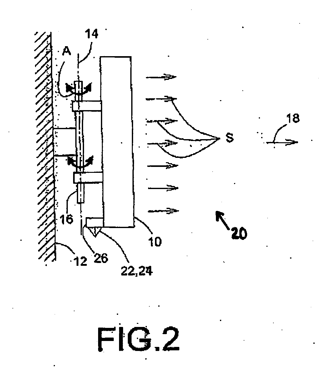
[0030] Referring to FIG. 1, there is shown a typical ground telecommunication antenna 10 installed on a high structure such as a building or a transmission tower 12. An antenna alignment system 20 in accordance with a preferred embodiment of the present invention is shown located adjacent the tower 12 on the ground for easy manipulation by an operator (not shown). The antenna 10 is pivotally mounted on the structure 12 about a generally vertical axis 14 of its rotation shaft 16 (see arrow A in FIG. 2) in order to be positionable thereabout to enable the adjustment of its azimuth orientation. Once in proper orientation, the antenna is lockable in place to remain in its adjusted orientation. It should be understood that the present invention could be utilized with any antenna structure so long as the antenna is movable, hinged, or otherwise adjustably mounted.

[0031] At least one prism target is temporarily and releasably mounted on the antenna 10 using a mounting support 26 (see FIG....


PUM


Abstract

A system and method of aligning an antenna with a predetermined azimuth direction. The method includes determining an antenna azimuth direction and moving the antenna from the antenna azimuth direction towards a predetermined azimuth direction so as to align said antenna. This is accomplished in response to processed positioning data received by a global positioning system (GPS) receiver dish from a GPS system where the receiver dish is locatable at predetermined first and second positions away from the antenna. The system includes at least two reference targets affixed to the antenna, a reference tool operatively coupled to the targets, and a GPS receiver dish connected to the reference tool. The receiver dish is in communication with a GPS system for processing positioning data received therefrom to determine an antenna azimuth direction of the antenna and thereby enable alignment of said antenna by moving the antenna with a predetermined azimuth direction.

Description

CROSS REFERENCE TO RELATED APPLICATIONS [0001] This application claims priority from U.S. Provisional Application Ser. No. 60 / 376,199 filed on Apr. 30, 2002, co-pending regular U.S. patent application Ser. No. 10 / 424,820 filed on Apr. 29, 2003, and U.S. Provisional Application Ser. No. ______ filed on Feb. 3, 2005 as Attorney Docket No. 604-BOl.US by Christian Bouchard and entitled “Antenna Alignment System And Method” each of which are herein incorporated by reference.FIELD OF THE INVENTION [0002] The present invention concerns an antenna, more particularly to a method of aligning the antenna with a predetermined azimuth direction. BACKGROUND OF THE INVENTION [0003] Wireless communications are now commonplace and rely on telecommunication antennae to transmit information to wireless devices such as mobile telephones including cellular, PCS, GSM, TDMA, CDMA, and the like. [0004] For maximum broadcast area coverage, the telecommunications antennae are located at high altitudes, such ...

Claims


Application Information

Patent Timeline
IPC IPC(8): G01S5/14G01S19/43G01S19/54H01Q1/12H01Q1/24
CPCG01S19/43G01S19/54H01Q1/125H01Q3/04H01Q1/246H01Q3/02H01Q1/1264
Inventor BOUCHER, CHRISTIAN
Owner 10322156 CANADA INC
Why Eureka
Try Eureka