Device for continuous or semi-continuous casting of metal material

a technology of metal materials and casting strands, applied in the direction of devices for continuous or semi-continuous casting of metal materials, etc., can solve the problems of reducing risk, harmful inclusions in finished cast strands, and affecting the magnitude and extension of the

Inactive Publication Date: 2005-09-22
ABB (SCHWEIZ) AG
View PDF2 Cites 0 Cited by
  • Summary
  • Abstract
  • Description
  • Claims
  • Application Information

AI Technical Summary

Benefits of technology

[0008] The thickness of the laminated layers may be elected with regard to the so-called depth of penetration of the magnetic field in the pole material. The depth of penetration may be calculated with a knowledge of the frequency of the magnetic field and the resistivity and permeability of the pole material. Advantageously, each of said layers comprises a plate shaped element having two substantially plane lateral surfaces which have an extension in a plane substantially perpendicular to the direction of current in the most closely located part of the coil. Thus, such an orientation of the layers is obtained that a minimal field constriction is obtained by the varying magnetic field and the influence on the varying magnetic field by the pole becomes substantially negligible.
[0009] According to another preferred embodiment of the present invention, the coil of the first arrangement and at least one of the poles of the second arrangement are provided in contact with each other. Hereby, a compact device is obtained. At the same time, a relatively small air-gap between the end surfaces of the poles provided towards each other is obtained. A small air-gap between the end surfaces of the poles results in that a less supply of electric energy is required for establishing a required static magnetic field acting on the melt in the casting mould. In order to reduce the air-gap further between the end surfaces of the poles directed to each other, one pole may at least comprise a recess which is arranged to receive said coil. Thus, a further compact unit is obtained. Advantageously, the coil and the poles constitute here an integrated part.

Problems solved by technology

Hereby the risk decreases that harmful inclusions arise in the finished cast strand in form of, for example, slag and gases.
However, the existence of the solid poles of the magnetic material of the electromagnetic brake in immediate vicinity of the coil fed with alternating current results in an influence of the magnitude and extension of the varying magnetic field.

Method used


Image

  • Device for continuous or semi-continuous casting of metal material
  • Device for continuous or semi-continuous casting of metal material
  • Device for continuous or semi-continuous casting of metal material

Examples


second embodiment

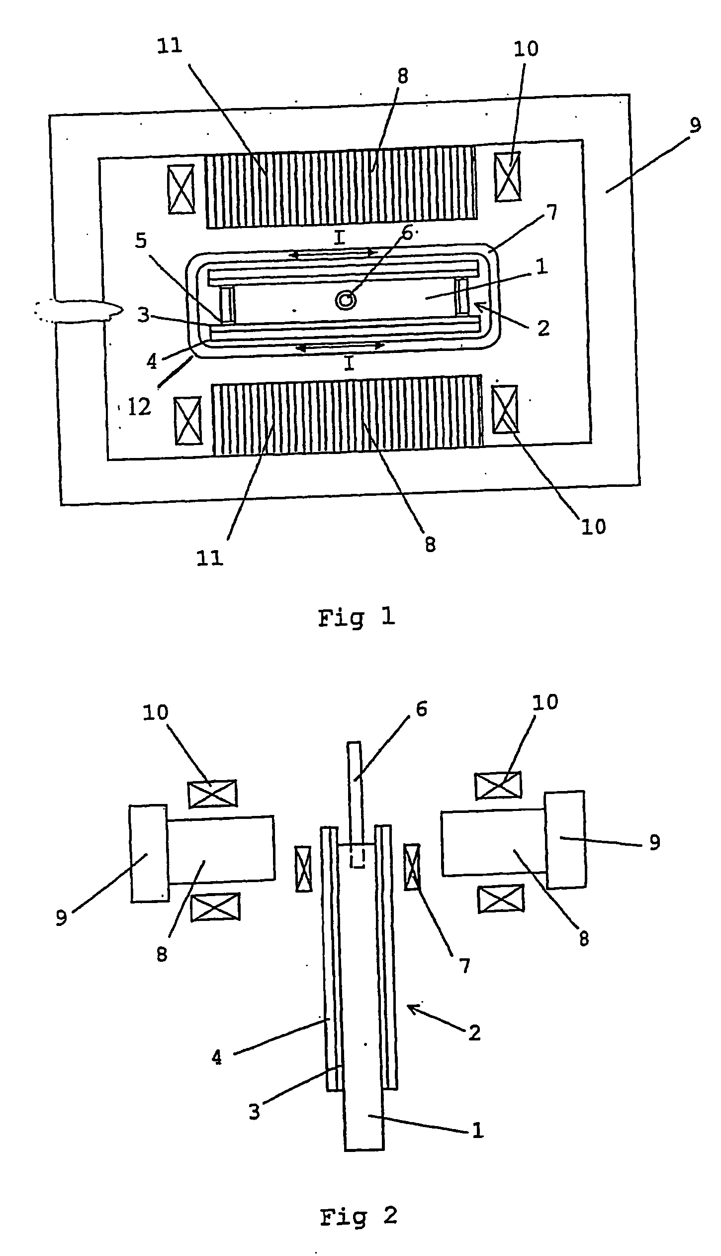
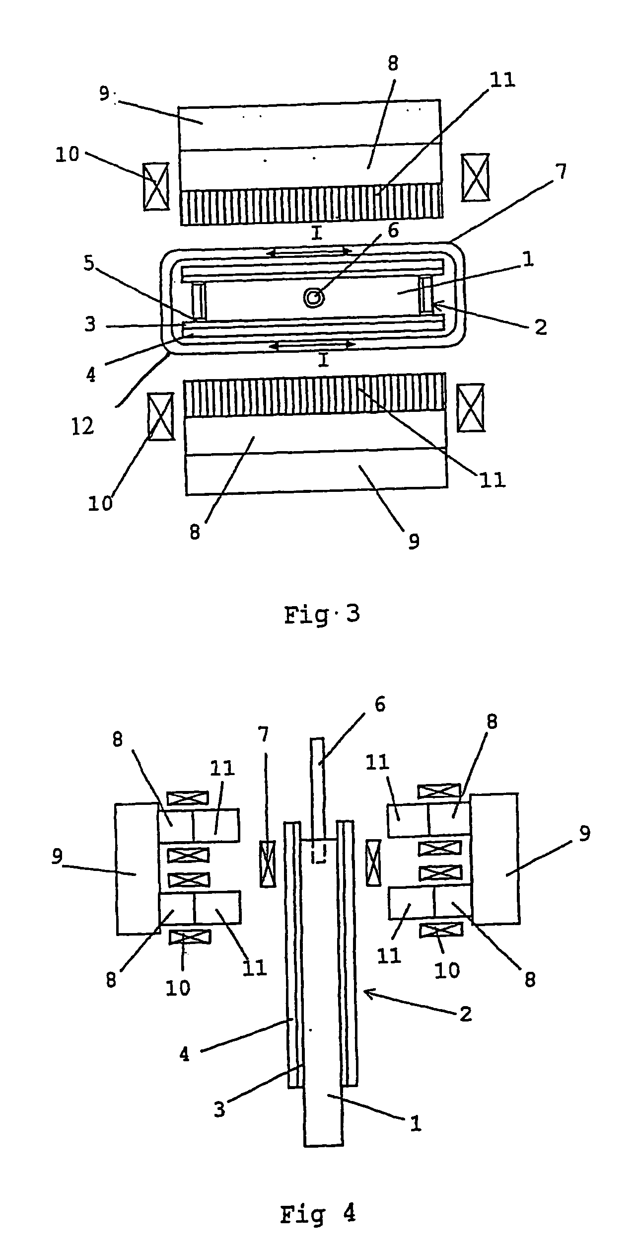
[0025]FIGS. 3 and 4 show the invention. In this case, the laminated portion 11 constitutes only a part of the pole 8. The laminated portion 11 is the part of the pole 8, which is, located nearest the coil 7 and consequently, the part of the pole 8 which is subjected to the heaviest varying magnetic field. In many cases, it is quite sufficient to laminate only such a portion 11 of the poles 8. The second arrangement comprises here four poles 8. Two poles 8 are provided at each side of the mould 2. A yoke 9 connects the two poles 8, which are provided at the same side of the mould 2 to each other. The poles 8 provided at the same side is located at different levels in relation to the mould 2 and have each an extension along substantially the whole width of the mould 2. The coils 10 are provided around each of the poles 8. By feeding the coils 10 with a direct current or a low-frequency alternating current, two parallel static or periodic low-frequency magnetic field at different level...

third embodiment

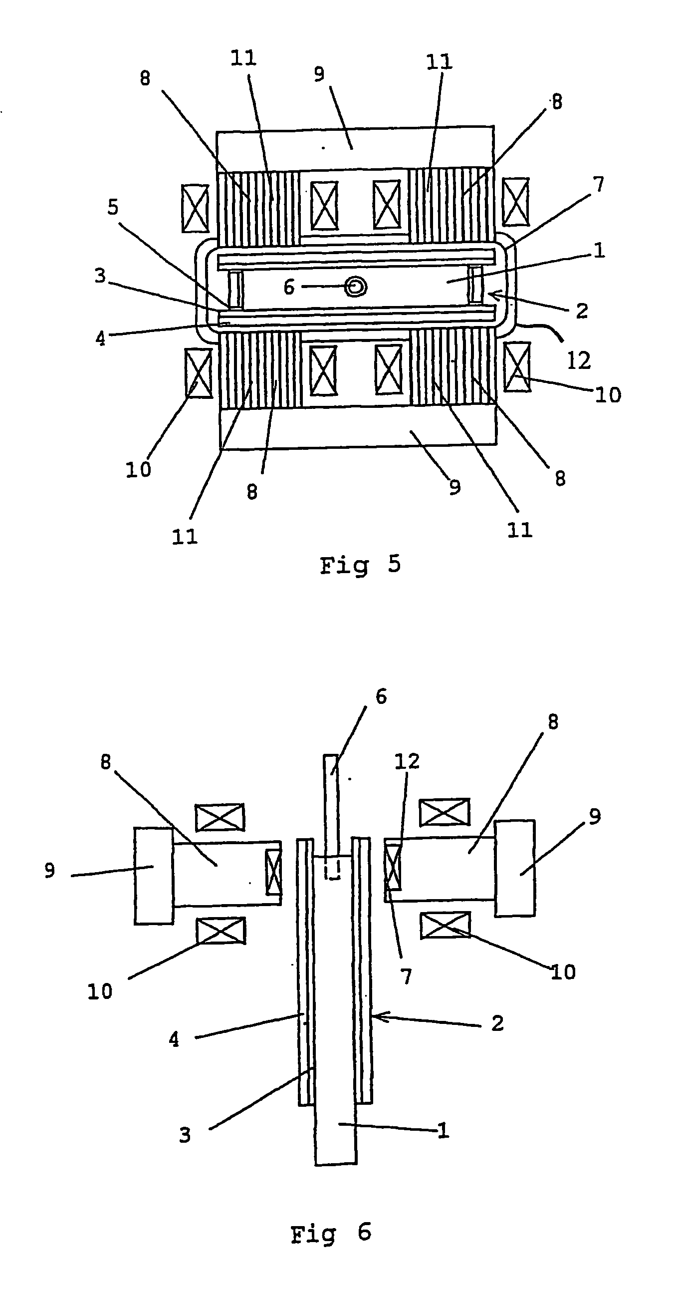
[0026]FIG. 5 and 6 show the invention. In this case the whole poles 8 comprises a laminated portion 11. The poles 8 are provided with recesses 12, which are arranged to receive the coil 7. Here, the poles 8 and the coil 7 consist of an integrated part. Thus, the device becomes compact and requires thereby a relatively small space. Furthermore, a smaller air-gap between the end surfaces of the poles 8 is obtained than in the above-described embodiments. By that fact, just as much electric energy does not need to be supplied to the coils 10 for providing a required magnetic field in the air-gap for the casting process. The second arrangement comprises here four poles 8. Two poles 8 are provided at each side of the mould 2. A yoke 9 connects the two poles 8, which are provided at the same side of the mould to each other. The two poles 8, which are provided at the same side, are located at the same level and have an extension along a part of the width of the mould 2. Coils 10 are provid...


PUM

PropertyMeasurementUnit
frequencyaaaaaaaaaa
magnetic fieldaaaaaaaaaa
resistivityaaaaaaaaaa

Abstract

The present invention relates to a device for continuous or semi-continuous casting of a metal material. The device comprises a first arrangement comprising a coil (7) having an extension around the casting mould (2) in an area, which is arranged to comprise molten metal material. The coil (7) is arranged to be fed with alternating current such that a varying magnetic field generated and is applied to the molten metal material in the casting mould (2). The device also comprises a second arrangement comprising at least two magnetic poles (8), which are provided at opposite sides of the casting mould (2). The poles (8) are arranged to supply a static or periodic low-frequency magnetic field to the molten metal material in the casting area. The poles (8) comprise at least a portion (11) which comprises a plurality of material layers which are electrically insulated from each other.

Description

BACKGROUND OF THE INVENTION AND PRIOR ART [0001] The present invention relates to a device for continuous or semi-continuous casting of a metal material, wherein the device comprises a casting mould which allows casting of a metal material to a desired shape, means for supplying a molten metal material to the casting mould, a first arrangement comprising a coil having an extension around the casting mould in a moulding area arranged to comprise molten metal material and which coil is arranged to be fed with an alternating current in such a way that a varying magnetic field is generated and is applied to the molten metal material in the casting mould and a second arrangement comprising at least two magnetic poles which are provided at opposite sides of the casting mould and which poles are arranged to supply a static or periodic low-frequency magnetic field to the molten metal material in the casting mould. [0002] The metal material used at such a casting process may be a pure metal ...

Claims


Application Information

Patent Timeline
Patent Type & Authority Applications(United States)
IPC IPC(8): B22D11/11B22D11/04B22D11/115
CPCB22D11/115
Inventor JACOBSON, NILSERIKSSON, JAN ERIKSVENSSON, ERIK
Owner ABB (SCHWEIZ) AG
Why Eureka
Try Eureka