Implantable Medical Cuff with Electrode Array

a medical cuff and electrode array technology, applied in the field of biomedical arts, can solve the problems of large power consumption, complicated control equipment, and inability to achieve attractive solutions, and achieve the effects of minimal tissue manipulation, minimal blood vessel constriction, and softness and pliability

a medical cuff and electrode array technology, applied in the field of biomedical arts, can solve the problems of large power consumption, complicated control equipment, and inability to achieve attractive solutions, and achieve the effects of minimal tissue manipulation, minimal blood vessel constriction, and softness and pliability

US20100241207A1Inactive Publication Date: 2010-09-23MED EL ELEKTROMEDIZINISCHE GERAETE GMBH

Image

  • Implantable Medical Cuff with Electrode Array
  • Implantable Medical Cuff with Electrode Array
  • Implantable Medical Cuff with Electrode Array

Examples


Embodiment Construction

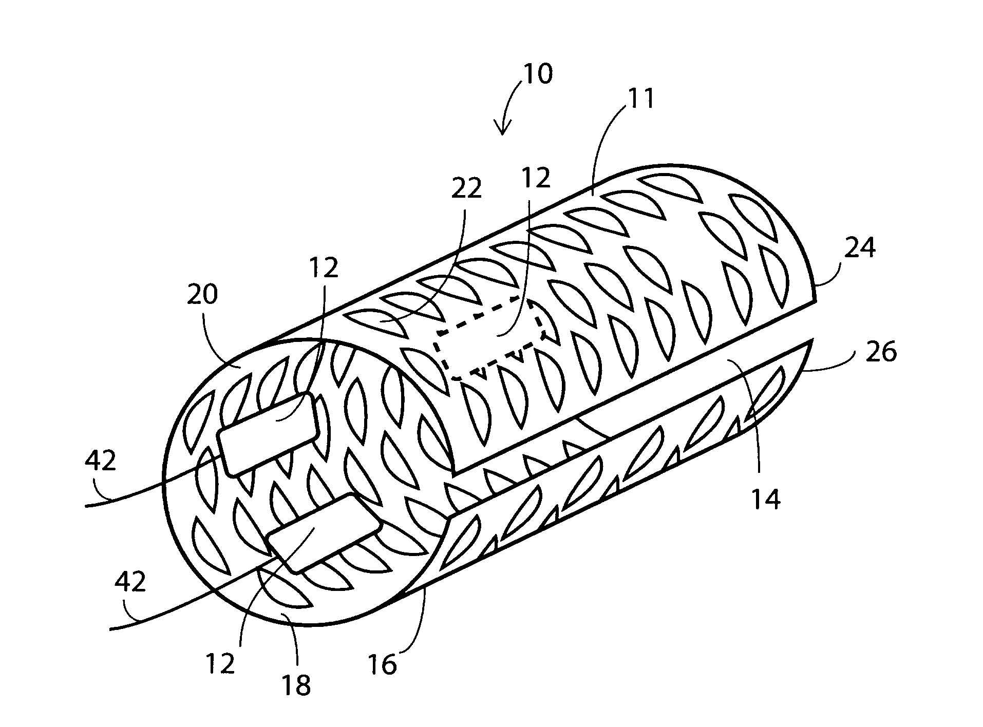
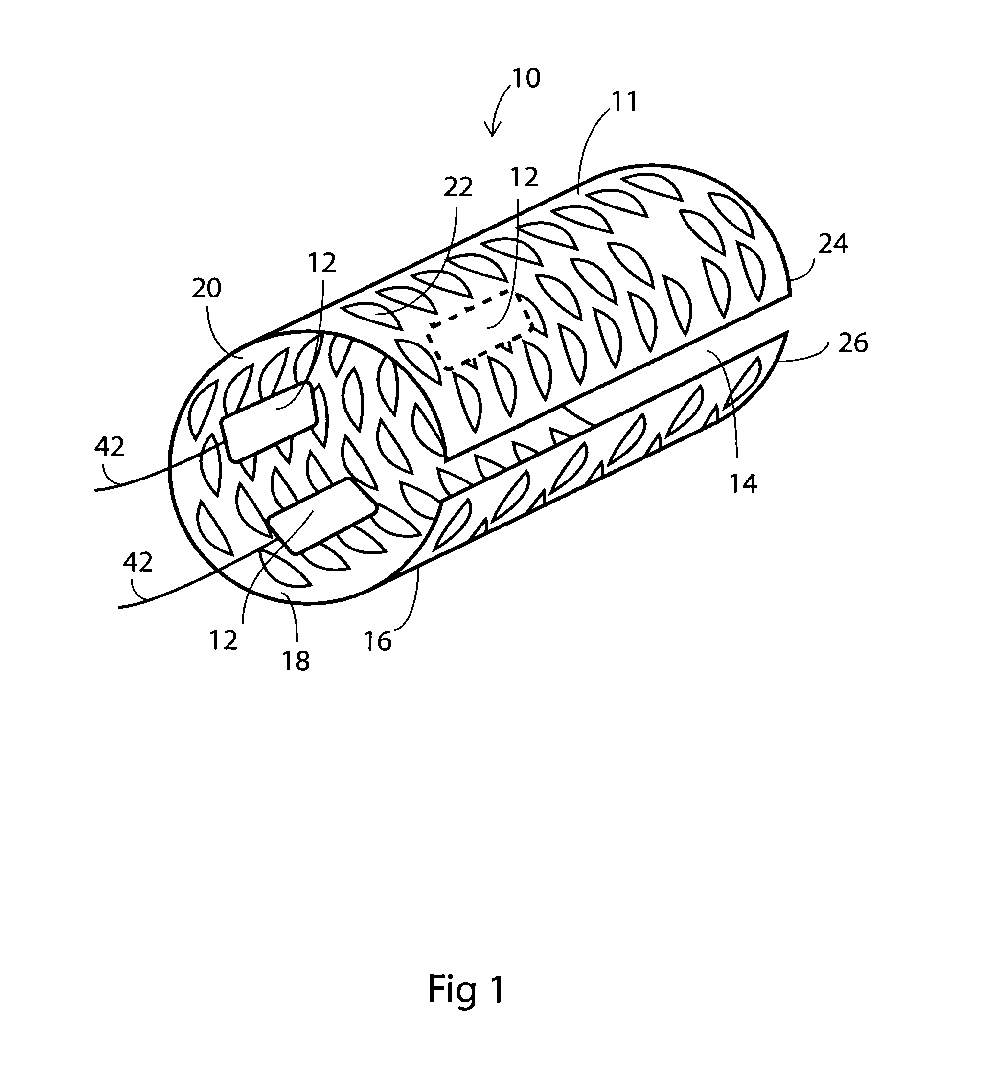
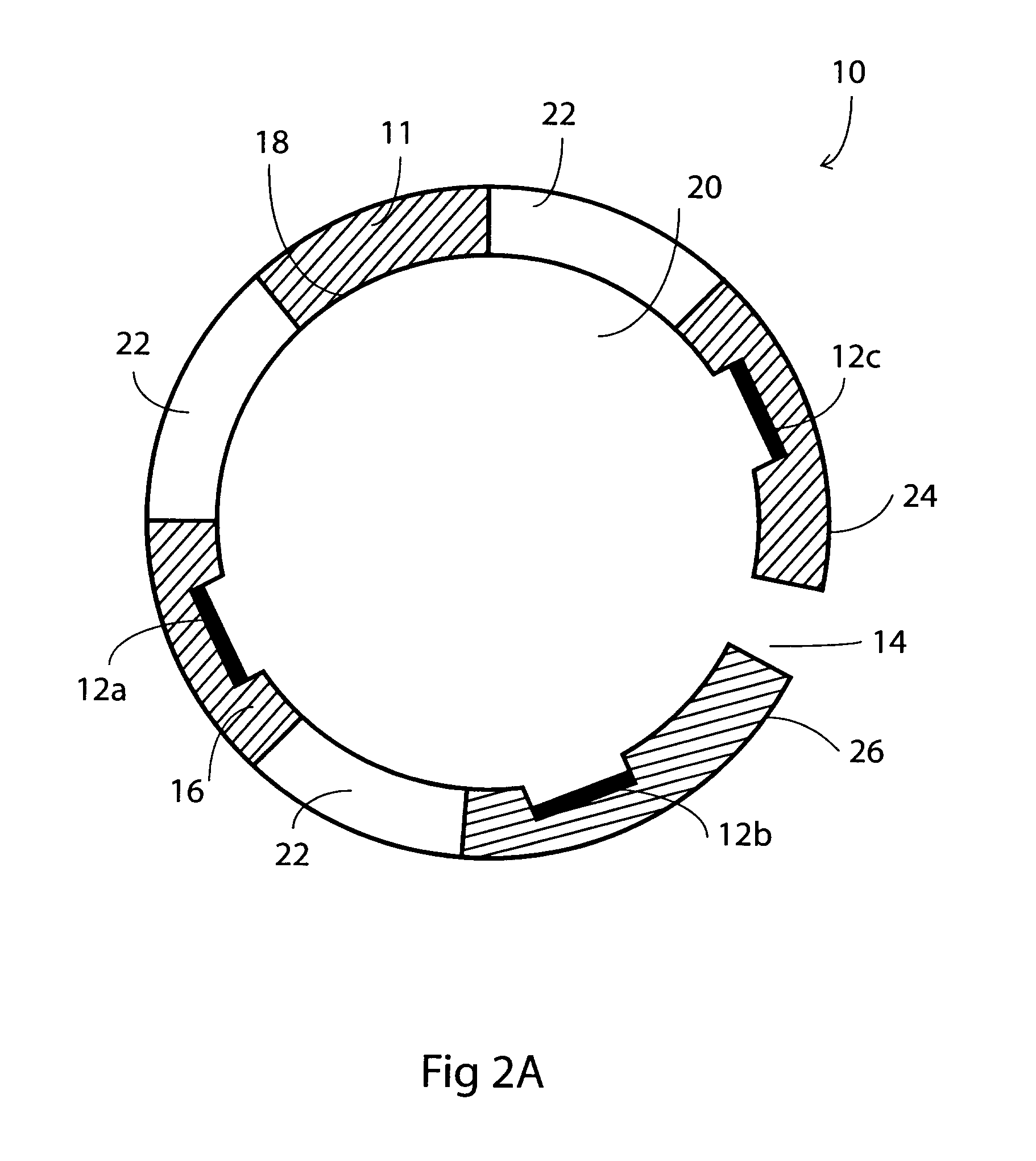
[0050]As shown in FIG. 1, a medical cuff 10 according to the present invention has a tubular cuff body 16 which has an inner surface 18 enclosing a generally cylindrical bore 20 for receiving a nerve or a portion of other body tissue (not shown). While this specification describes the cuff in association with a nerve, it is understood that the cuff is also adapted for use with other soft tissue, such as muscle. The cuff body 16 is formed from a web 11 of biocompatible film that is wound into a generally tubular configuration. Web 11 has opposed longitudinal edges 24, 26 allowing cuff body 16 to be opened, placed around an elongated portion of body tissue, and sealed with the tissue passing through the bore 20.

[0051]At least one aperture, such as slit 22, is established along the cuff body 16 through web 11 by any suitable method, such as laser cutting. Preferably, a plurality of such slits is distributed throughout web 11. The slits 22 allow fluids within the body to permeate the me...


PUM


Abstract

An implantable medical assembly comprising at least one electrode carried on an inside surface of a web comprising a biocompatible film wound into a generally tubular configuration, the film containing a plurality of distinct apertures distributed throughout the web to increase its flexibility and to create a means by which biological fluids can penetrate the assembly. The assembly may further comprise at least one wire connected to the electrode to provide a stimulation signal.

Description

CROSS REFERENCE TO RELATED APPLICATIONS[0001]This application is related to U.S. patent application Ser. No. 10 / 348,970 filed Jan. 23, 2003 entitled “Implantable Medical Assembly”, which is incorporated herein by reference.[0002]This application is related to U.S. patent application Ser. No. 10 / 623,639 Jul. 22, 2003 entitled “Implantable Electrical Cable and Methods of Making”, which is also incorporated herein by reference.FIELD OF THE INVENTION[0003]The present invention relates to the biomedical arts and in particular to implantable electrode arrays. More particularly, this invention relates to an implantable medical cuff with an electrode array which is to be applied to body tissue to provide an effective electrical connection therewith, for sensing or stimulating purposes.BACKGROUND OF THE INVENTION[0004]This invention relates to cuffs for surgical implantation in animals and humans. Cuffs according to the invention have particular application as nerve cuffs and can be made ele...

Claims


Application Information

Patent Timeline
23 Sep 2010
Publication
US20100241207A1
IPC
A61N1/05
CPC
A61B5/0422; A61B5/1473; A61N1/056; A61N1/0556; A61N1/05; A61B5/287
Inventors
BLUGER, HENRY