Balance with a weighing compartment

a weighing compartment and balance technology, applied in the field of balance with a weighing compartment, can solve the problems of high precision, weighing errors, and design that is still not entirely satisfactory, and achieve the effects of simple manner, minimum manipulation, and good accessibility

Inactive Publication Date: 2005-06-21
METTLER TOLEDO GMBH
View PDF3 Cites 7 Cited by
  • Summary
  • Abstract
  • Description
  • Claims
  • Application Information

AI Technical Summary

Benefits of technology

[0007]It is therefore the object of the present invention, to provide a balance with good accessibility to the weighing compartment so that conduits into the weighing compartment can be installed in a simple manner with a minimum of manipulation.SUMMARY OF THE INVENTION
[0010]The availability of cutout passages offers a simple way of running electrical supply or data cables or conduits for fluids and gases through the cutout passages, to secure the cables and conduits in the cutout openings by means of special clip holders, and to seal the openings against air drafts. Special configurations of the clip-on devices, e.g., as holder elements, expand the range of their possible uses.
[0011]A preferred embodiment is configured so that the side walls, the front wall, and the top cover panel can be individually separated by hand from the balance by simply pulling at them lightly to tilt them outwards, e.g., for easy cleaning of the wall plates, which are normally made of glass. When they are in their working position, the walls are positively locked into place in guide elements of the guiding device. The same hand movement is used to unlock each of the walls. Besides making the weighing compartment easy to disassemble for cleaning, the concept of integrating the holder arrangements of the slidable walls in the guiding devices also accomplishes the objective of making the weighing compartment freely accessible and of allowing an unobstructed view of the weighing pan even when the weighing compartment is closed, with no sight-blocking frame members being in the way. In addition, the inventive concept offers the possibility to set the front wall panel as well as the movable wall panels into a stable inclined position through a simple manual procedure.

Problems solved by technology

To a certain extent, the walls are unobstructed by the frame members so that the operator has a better view of the interior of the housing, but for some applications, this design is still not entirely satisfactory.
One drawback is that the upper part of the frame is still a required element, and another concern is that the locking elements, which have to be manufactured with high precision, require a certain amount of manipulation in order to align them with the recesses in which they are received.
In state-of-the-art balances, if conduits, hoses, or other connections have to be introduced into the weighing compartment in a flexible, non-permanent arrangement, a slidable side wall or the top cover panel has to stay at least partially open during the weighing process, because the rigid frames and complicated guiding devices do not allow the walls to be provided with individual, easily accessible conduit passages.
However, leaving a wall open can cause errors in the weighing result.
In essence, known balances suffer from the drawback that they do not simultaneously allow free, unrestricted access to the weighing compartment as well as an unobstructed view of the weighing pan.
Simultaneous access from the side and from above is not possible, a problem that applies in particular to the accessibility for conduits, hoses or other connections.

Method used


Image

  • Balance with a weighing compartment
  • Balance with a weighing compartment
  • Balance with a weighing compartment

Examples


Embodiment Construction

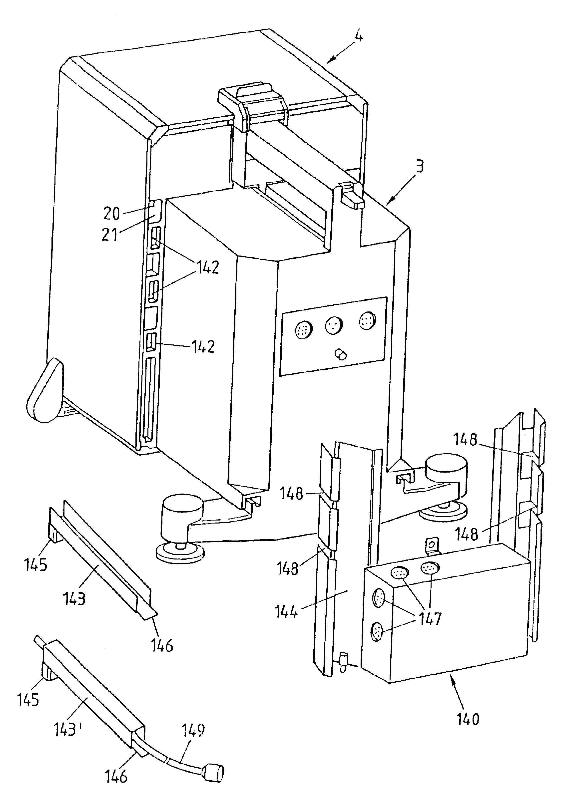
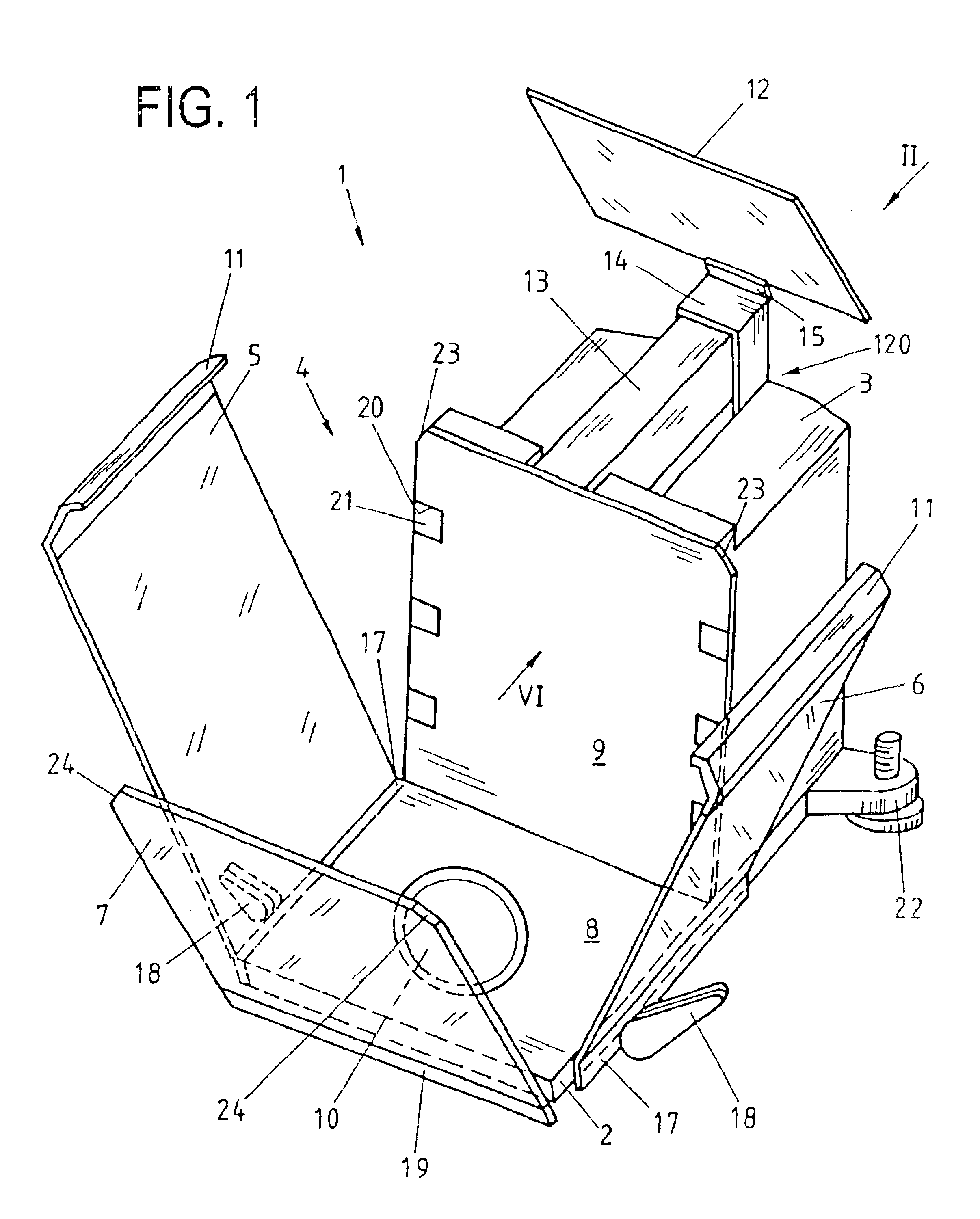
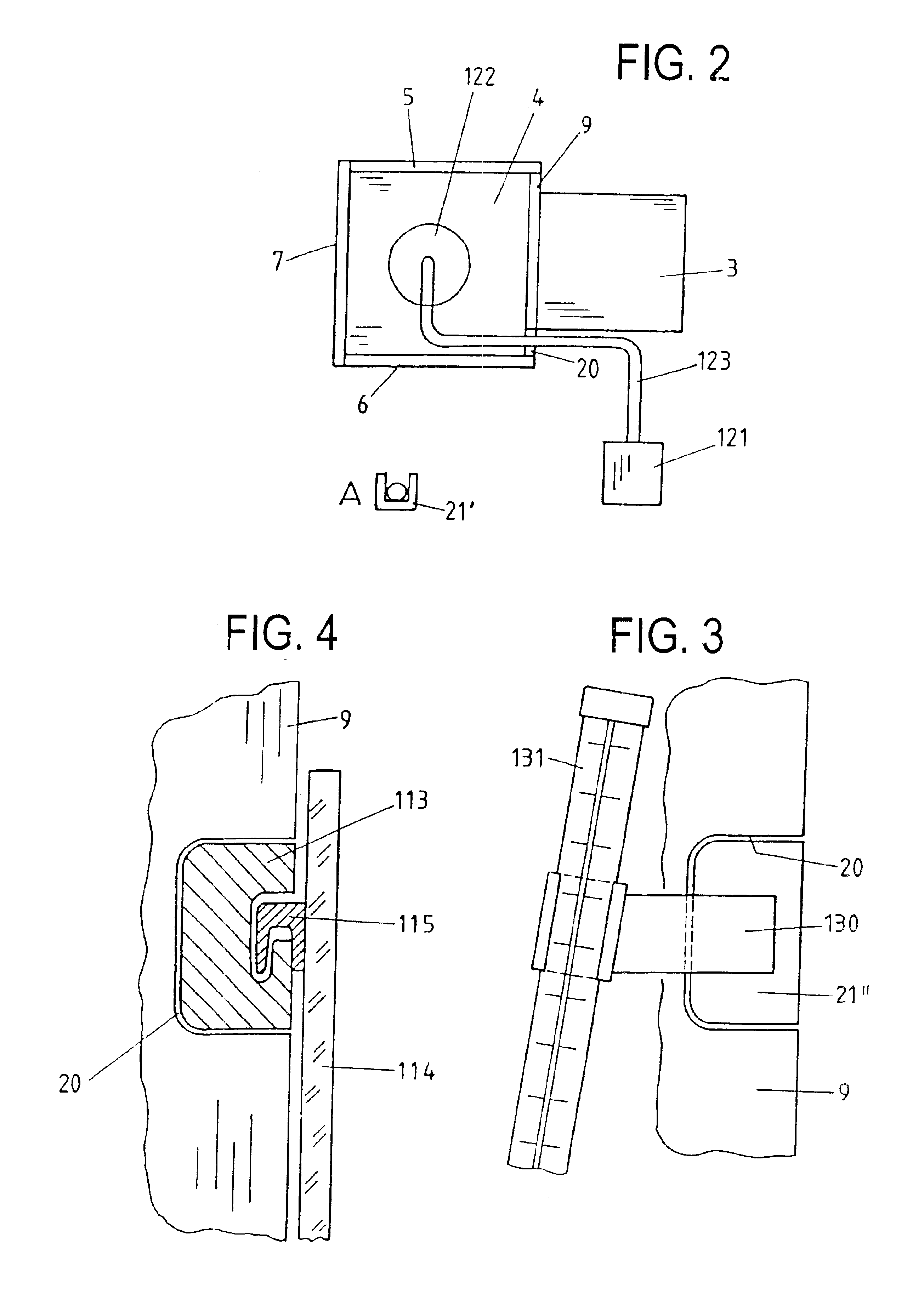
[0019]A balance according to FIG. 1 has a stationary part with a floor compartment 2 that contains a portion of the working system of the balance, a housing 3 that essentially contains the drive mechanism, and a weighing compartment 4. The rear wall 9 and the floor 8 of the weighing compartment 4 are formed by the stationary part. The weighing compartment 4 is further enclosed by the side walls 5, 6, the front wall 7, and the top cover panel 12, which serve as a draft shield. The floor 8 has a pass-through opening for the carrier of the weighing pan 10. However, the weighing pan can also be supported by an L-shaped cantilever arm that is attached to a coupling arrangement that passes through the rear wall of the weighing compartment, as described in EP 1 195 586 A1. The different designs of the weighing pan and / or the features of the weighing compartment described in the reference just mentioned are likewise applicable to the balance described herein.

[0020]Preferably, the balance 1 ...


PUM


Abstract

A balance (1) has a weighing compartment (4) that borders on a stationary part (8, 9) of the balance and is otherwise enclosed by at least one side wall panel (5, 6), a front wall panel (7), and a top cover panel (12). At least one of the panels is slidable by means of a guiding device (17, 20) to open and close the weighing compartment (4). The balance (1) further has cutout passages (20) in the side wall panels (5, 6), the front wall panel (7), the top cover panel (12), and / or the rear wall of the weighing compartment, so that cables and / or conduits can be introduced from the outside into the weighing compartment.

Description

CROSS-REFERENCE TO RELATED APPLICATION[0001]This application is a divisional of U.S. patent application Ser. No. 09 / 957,933, filed Sep. 21, 2001 now U.S. Pat. No. 6,686,545.BACKGROUND OF THE INVENTION[0002]The present invention relates to a balance with a weighing compartment that borders on a stationary part of the balance and is otherwise enclosed by at least one side wall, a front wall, and a top cover panel, where at least one of the walls and / or the top cover panel is slidable by means of a guiding device to open and close the weighing compartment.[0003]A known balance of this kind, as described for example in the European patent application EP-A-0 234 008, has a weighing pan and a weighing compartment that encloses the weighing pan on all sides, with a stationary front glass wall, rearward-sliding side walls, a rearward-sliding top cover panel, and a connector that joins the side walls with the top cover panel. The connector is configured so that when a side wall and / or the to...

Claims


Application Information

Patent Timeline
Patent Type & Authority Patents(United States)
IPC IPC(8): G01G21/28G01G21/00G01G21/30
CPCG01G21/286
Inventor LUCHINGER, PAULFRINGELI, EDUARDMEISTER, BEAT
Owner METTLER TOLEDO GMBH
Why Eureka
Try Eureka