
Diesel engine exhaust gas purification method and exhaust gas purification system

a technology of exhaust gas purification and diesel engine, which is applied in the direction of machines/engines, electrical control, separation processes, etc., can solve the problems of deterioration in drivability of vehicles, and inability to directly employ a three-way catalyst in a stoichiometric atmosphere, etc., to suppress deterioration in fuel consumption and drivability. drivability

Active Publication Date: 2015-12-29
ISUZU MOTORS LTD
View PDF9 Cites 0 Cited by
  • Summary
  • Abstract
  • Description
  • Claims
  • Application Information

AI Technical Summary

Benefits of technology

[0008]An object of the present invention is to provide a diesel engine exhaust gas purification method and an exhaust gas purification system which can purify exhaust gas while suppressing deteriorations in drivability and fuel consumption.
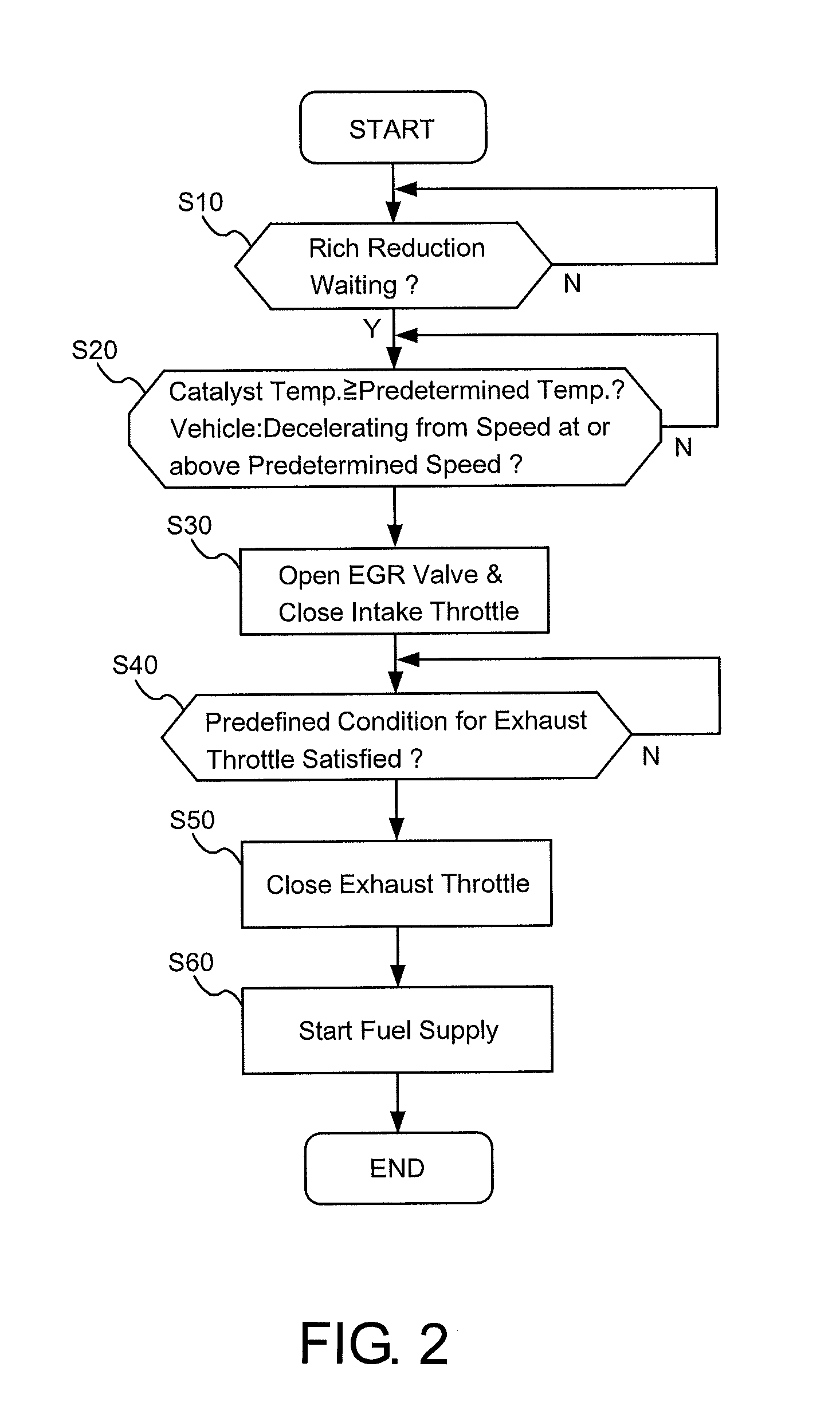
[0013]According to the diesel engine exhaust gas purification method and the exhaust gas purification system of the present invention, the state of the exhaust gas is changed into rich when the vehicle is decelerating from a speed at or above the predetermined speed, thus suppressing deterioration in drivability. Further, since the amount of the exhaust gas is throttled when the state of the exhaust gas is changed into rich, less fuel is needed to be supplied to change the state of the exhaust gas into rich, thus suppressing deterioration in fuel consumption.

Problems solved by technology

This is because since the exhaust gas of the diesel engine is a lean atmosphere in terms of the air-fuel ratio, it is impossible to directly employ a three-way catalyst used in a stoichiometric atmosphere as in the case of the gasoline engine.
However, the former reduction of the amount of air-intake might lead to deterioration in drivability of a vehicle, and the latter fuel supply might lead to deterioration in fuel consumption.

Method used


Image

  • Diesel engine exhaust gas purification method and exhaust gas purification system
  • Diesel engine exhaust gas purification method and exhaust gas purification system
  • Diesel engine exhaust gas purification method and exhaust gas purification system

Examples


Embodiment Construction

[0017]Hereinafter, a description will be given of an embodiment of the present invention with reference to the drawings.

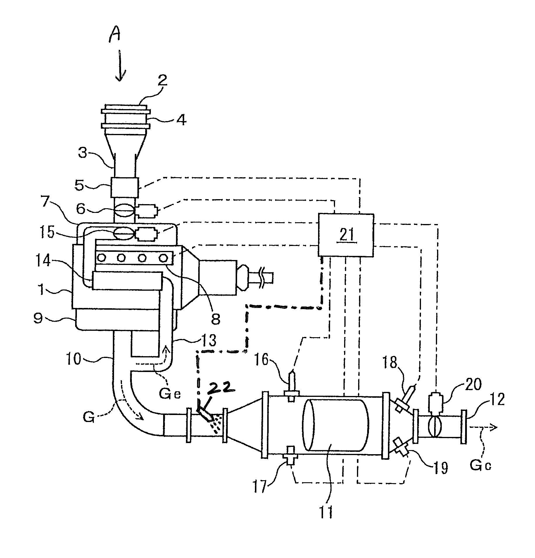
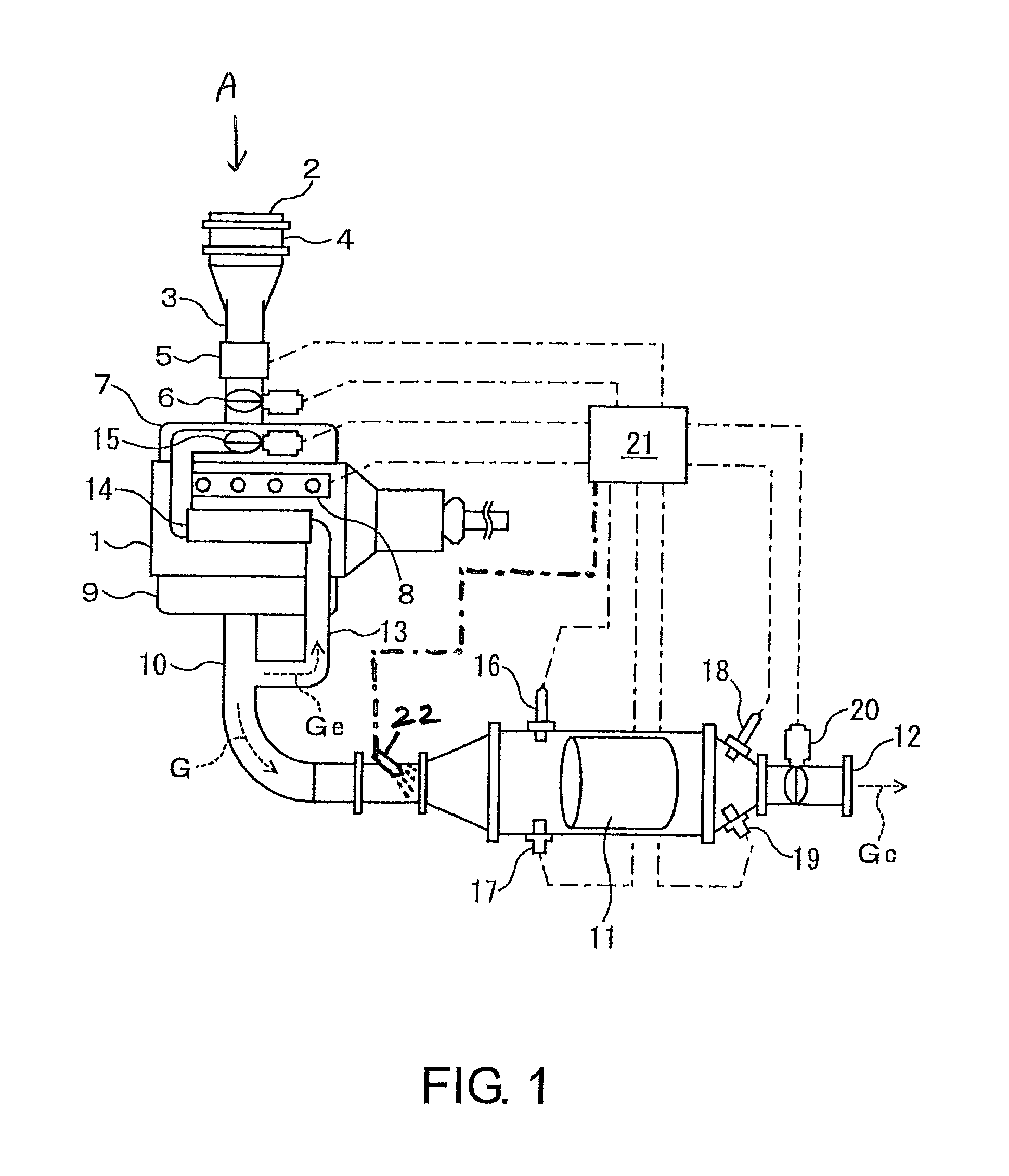
[0018]FIG. 1 shows a diesel engine exhaust gas purification system according to an embodiment of the present invention. In a diesel engine 1 equipped with this diesel engine exhaust gas purification system, air A taken from an inlet port 2 into an intake passage 3 sequentially passes through an air cleaner 4 and amass air flow sensor (MAF sensor) 5, and after the amount of air-intake is regulated with an intake throttle 6, is supplied into each cylinder from an intake manifold 7. Then, after fuel injected through a common rail injection system 8 is burned, the air is discharged from an exhaust manifold 9 into an exhaust passage 10 as exhaust gas G. Then, it passes through an NOx occlusion reduction catalyst 11 and is discharged from an exhaust port 12 as purified exhaust gas Gc. Further, part of exhaust gas G is diverted into an EGR passage 13 as EGR gas Ge, and af...


PUM

PropertyMeasurementUnit
temperatureaaaaaaaaaa
speedaaaaaaaaaa
timeaaaaaaaaaa

Abstract

An exhaust gas purification method of a diesel engine, which purifies exhaust gas while suppressing deterioration in drivability and fuel consumption, including when exhaust gas enters a rich reduction state, opening an EGR valve and closing an intake throttle, if a temperature of an NOx occlusion reduction catalyst is at or above a predetermined temperature, and a vehicle having a diesel engine is decelerating from a speed at or above a predetermined speed, and then closing an exhaust throttle provided downstream of the NOx occlusion reduction catalyst and supplying fuel to the NOx occlusion reduction catalyst as a reductant.

Description

CROSS-REFERENCE TO RELATED APPLICATIONS[0001]This application claims the benefit under 35 U.S.C. Section 371, of PCT International Application No. PCT / JP2012 / 079342, filed Nov. 13, 2012, and under 35 U.S.C. §119 of Japanese Application No. 2011-271292, filed Dec. 12, 2011, the contents of which are incorporated herein by reference.BACKGROUND OF THE INVENTION[0002]1. Technical Field[0003]The present invention relates to an exhaust gas purification method and an exhaust gas purification system, and more particularly to a diesel engine exhaust gas purification method and an exhaust gas purification system which can purify exhaust gas while suppressing deteriorations in drivability and fuel consumption.[0004]2. Background Art[0005]In a diesel engine exhaust gas purification system, an NOx occlusion reduction catalyst is used in order to reduce nitrogen oxides (NOx) contained in exhaust gas, unlike a gasoline engine (see Japanese patent application Kokai publication No. 2009-275561, for ...

Claims


Application Information

Patent Timeline
Patent Type & Authority Patents(United States)
IPC IPC(8): F01N3/00F01N9/00F02D21/08F01N3/20F02D41/02F01N3/08B01D53/94F02D41/00F02D9/04F02D41/18
CPCF01N9/00F01N3/0842F01N3/20F02D21/08F02D41/0005F02D41/0052F02D41/0055F02D41/0275B01D53/9495Y02T10/47B01D53/9409B01D2251/208B01D2255/91B01D2258/012F01N2240/36F01N2560/026F02D9/04F02D41/18F02D2041/0017F02D2200/0802F02D2200/501Y02T10/42F02D2041/0022Y02T10/40
Inventor NAGAOKA, DAIJINAKADA, TERUOYUZA, HIROYUKI
Owner ISUZU MOTORS LTD
Learn More