

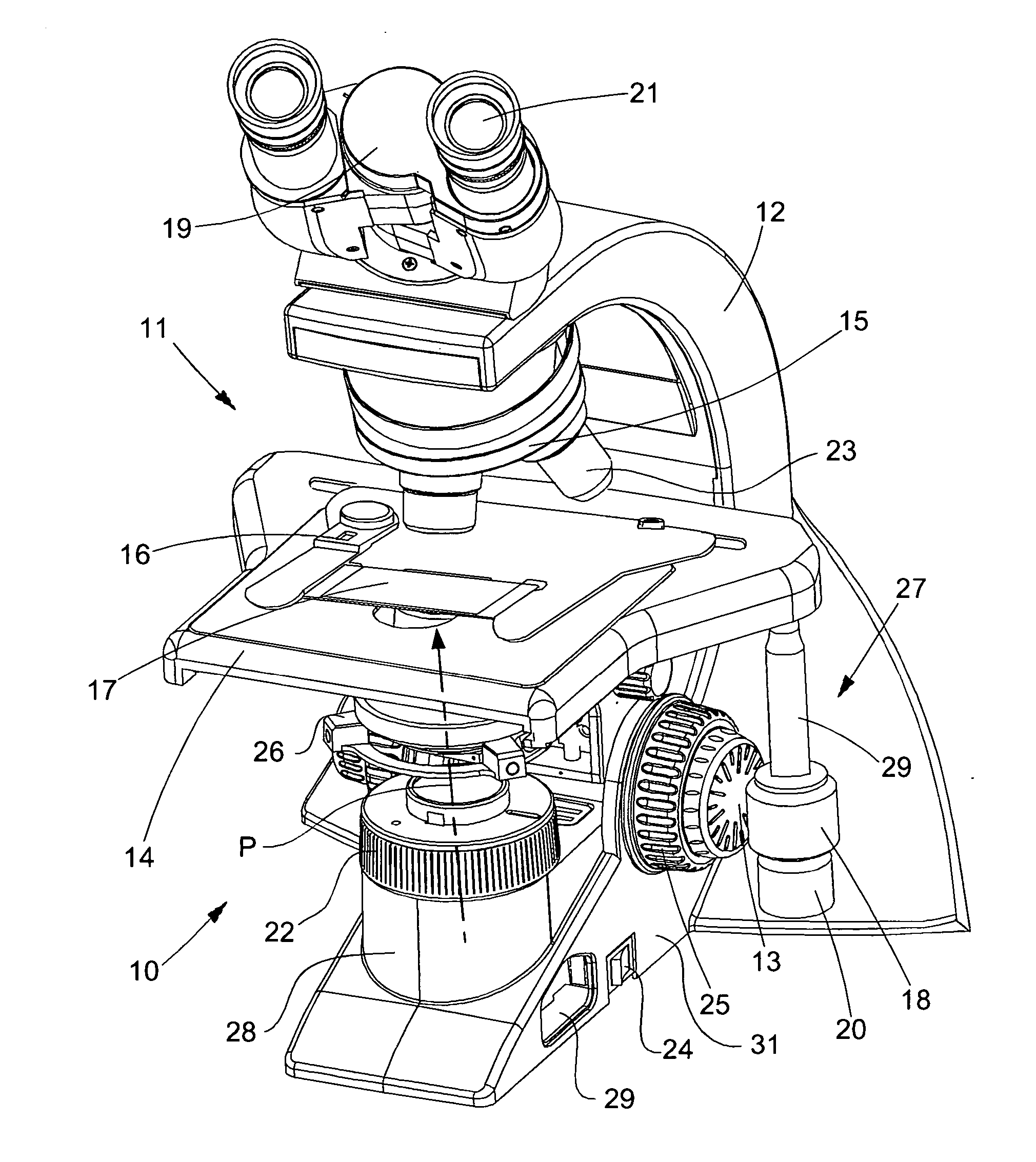
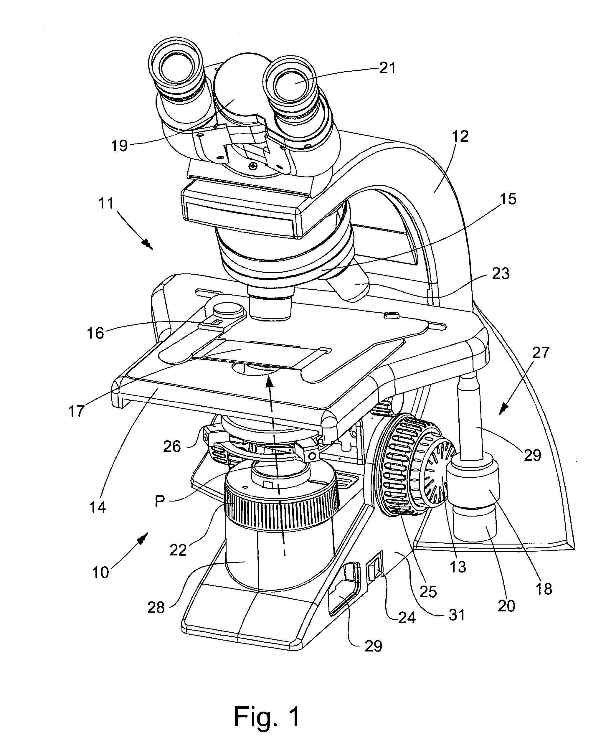
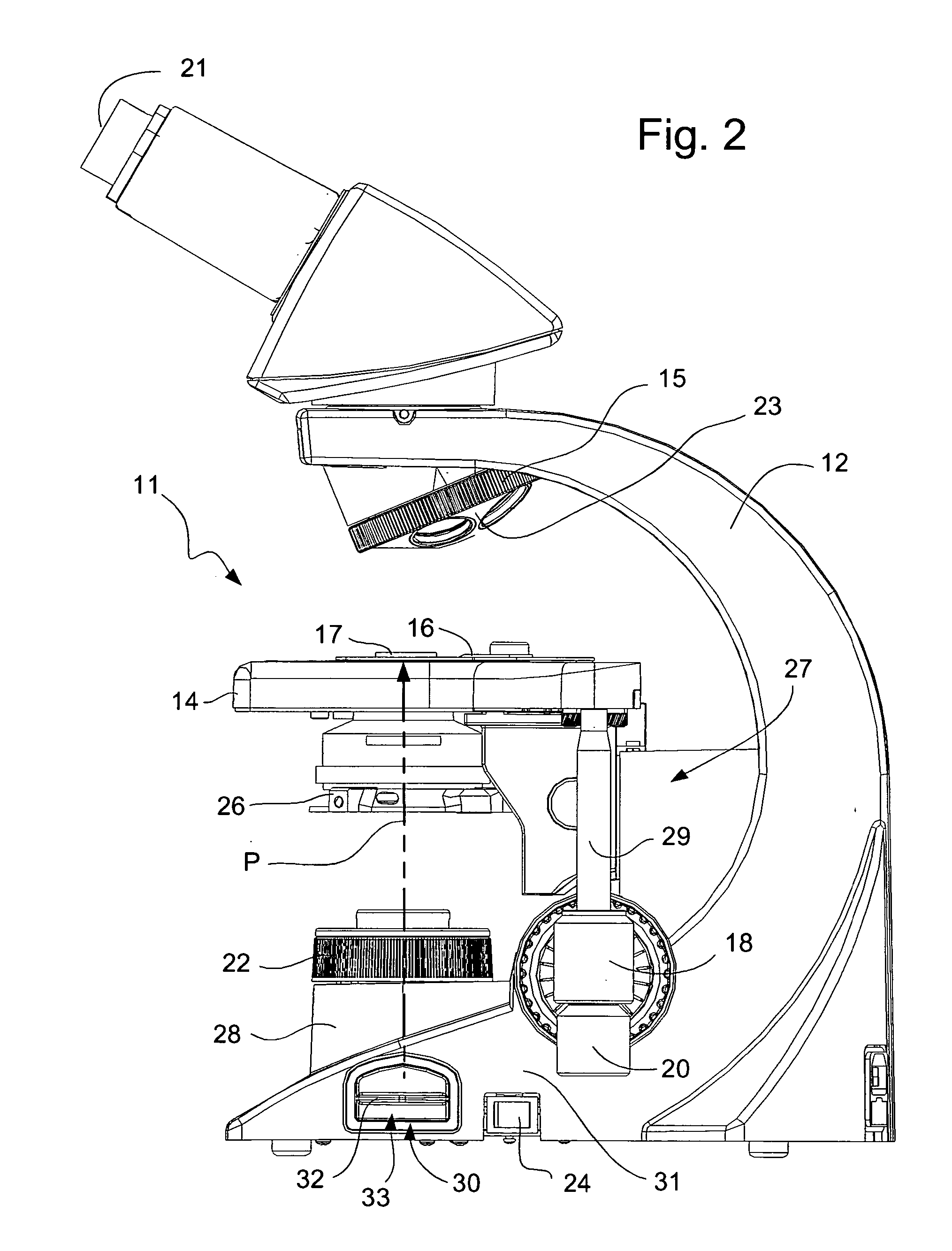
Lamp assembly for a microscope
- Summary
- Abstract
- Description
- Claims
- Application Information
AI Technical Summary
Benefits of technology
Problems solved by technology
Method used
Image

Examples
Embodiment Construction
[0027] It should be appreciated at the outset that while the present invention relates to an “Lamp Assembly for a Microscope”, the Assignees of the present application for patent have developed certain other improvements to microscopes described in United States patent applications entitled “Interchangeable Microscope Stage Drive Assembly”, “Releasable / Interchangeable Fine Focus Knob for a Microscope”, “Ergonomically Arranged Object Adjustment Controls”, “Shielded-Ergonomic Microscope Stages”, “Heat Sink Assembly for a Microscope” and “Means for Transporting a Microscope”, which applications are filed concurrently herewith by the Assignees of the present application for patent, which Applications are incorporated herewith by reference in their entireties.
[0028] Additionally, it should be appreciated that like drawing numbers on different drawing views identify identical structural elements of the invention. While the present invention is described with respect to what is presently ...
PUM
 Abstract
Description
Claims
Application Information