Vertical guide mechanism of stone sawing machine

A vertically oriented, stone sawing machine technology, applied in stone processing equipment, work accessories, manufacturing tools, etc., can solve the problems affecting the structural stability of the stone sawing machine, the accuracy of stone breaking and cutting, and the poor sliding effect of up and down. Replacement process and maintenance costs, reduced transportation costs, and the effect of avoiding noise and vibration

Pending Publication Date: 2018-09-11
佛山市顺德区悍天睿数控机械有限公司 +1
View PDF1 Cites 0 Cited by
  • Summary
  • Abstract
  • Description
  • Claims
  • Application Information

AI Technical Summary

Problems solved by technology

[0002] Chinese patent document No. CN202114822U disclosed a transmission structure of a large-scale stone sawing machine on January 29, 2011. It includes a saw frame that slides up and down between the front column and the rear column, and the saw frame is provided with several saw blades. / article; the main transmission structure includes the main shaft connected with the saw frame, the main shaft is connected with the driving motor; The speed of the main shaft is the same; the main shaft of this structure is driven by the eccentric block and the connecting rod and the saw frame to realize the up and down movement of the saw frame. Moreover, both sides of the saw frame are connected with synchronously running main shafts, and each main shaft is driven by a drive motor respectively. The load is shared to each driving motor; however, the saw frame is in a suspended state, and only slides up and down between the front and rear columns through the transmission of the main transmission structure, and the up and down sliding effect is poor, resulting in stones being cut during the sawing operation. Problems such as noise and vibration that are easy to occur during the process will cause the stone to break or the cutting accuracy is not high, and will also affect the structural stability of the stone saw machine. Waste of energy consumption, increase production cost

Method used


Image

  • Vertical guide mechanism of stone sawing machine
  • Vertical guide mechanism of stone sawing machine
  • Vertical guide mechanism of stone sawing machine

Examples


Embodiment Construction

[0031] The present invention will be further described below in conjunction with the accompanying drawings and embodiments.

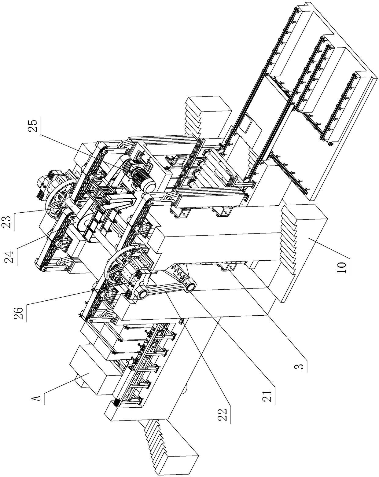
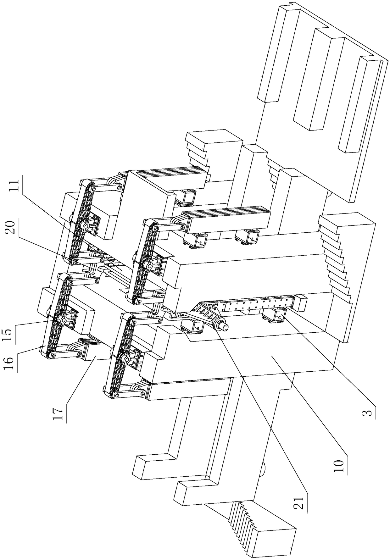
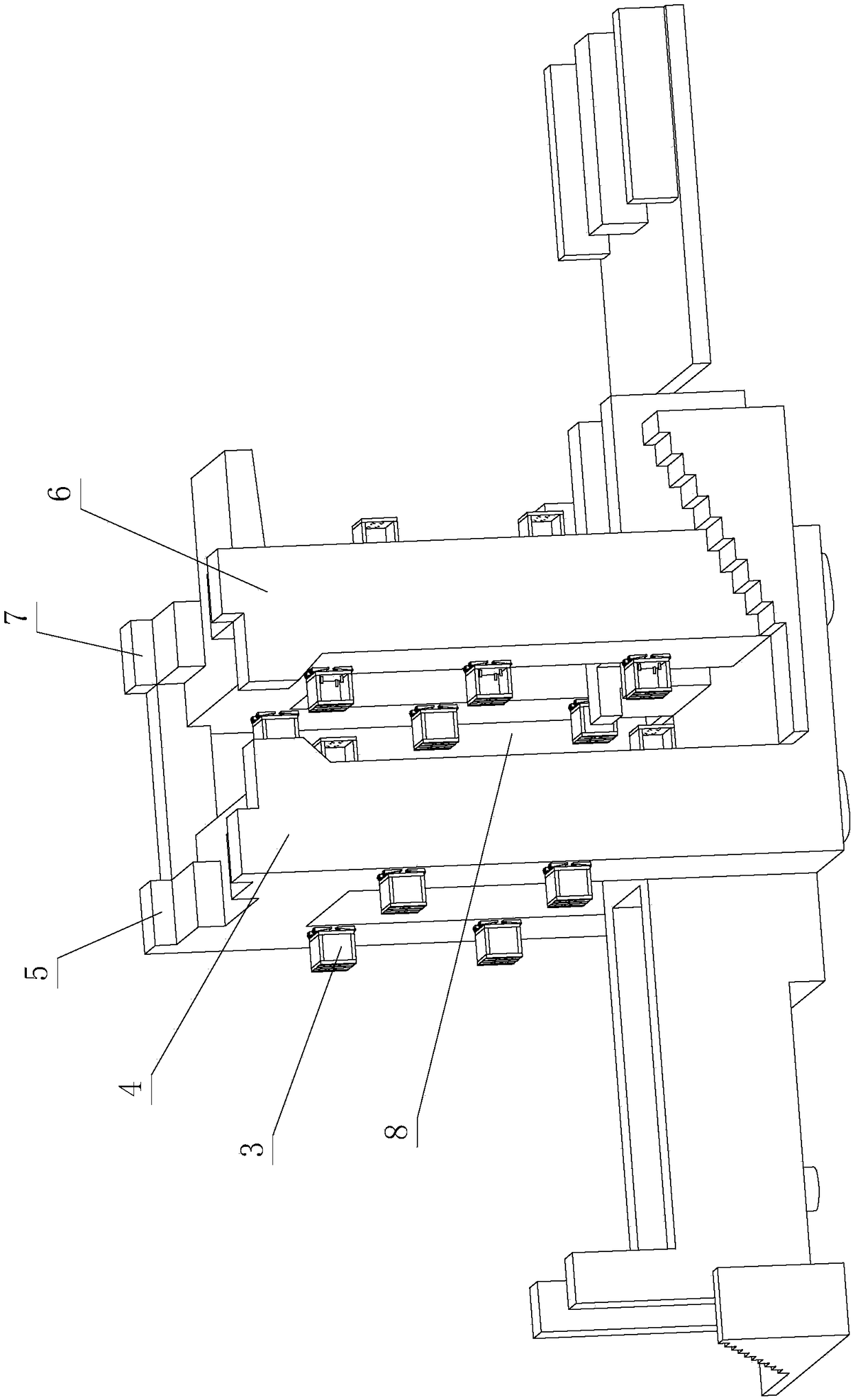
[0032] see Figure 1-Figure 9 , the vertical guiding structure of the stone sawing machine includes a foundation 10 and a stone sawing device arranged on the foundation 10, a stone sawing driving device, a stone sawing power auxiliary device, and a stone pushing device A, and the stone sawing device includes a saw frame and a saw blade, The saw frame is a combination, and a hollow part 1 is arranged in the middle position, and the saw blade is vertically arranged on the hollow part 1, and the saw frame, the stone saw driving device and the saw stone power auxiliary device are mutually driven and connected; wherein, the saw frame and the foundation 10, and / or between the stone-sawing power auxiliary device and the foundation 10, a vertical guide assembly is also arranged; the saw frame reciprocates vertically up and down through the cooperation of the st...


PUM


Abstract

The invention discloses a vertical guide mechanism of a stone sawing machine. The structure comprises a foundation, a stone sawing device, a stone sawing drive device, a stone sawing power auxiliary device and a stone pushing device, wherein the stone sawing device, the stone sawing drive device, the stone sawing power auxiliary device and the stone pushing device are arranged on the foundation, the stone sawing device comprises a sawing frame and a sawing blade, the sawing frame is a combination body, an open part is arranged in the middle of the sawing frame, the sawing blade is vertically arranged on the open part, the sawing frame, the stone sawing drive device and the stone sawing power auxiliary device are in drive connection, a vertical guide assembly is arranged between the sawingframe and the foundation and/or the stone sawing power auxiliary device and the foundation, the sawing frame slides on the foundation in a vertical up and down reciprocating guide manner through cooperation of the stone sawing drive device, the stone sawing power auxiliary device and the vertical guide assembly, and during vertical up and down reciprocating guide sliding, through the sawing blade,the stone sawing work is achieved; and/or the stone sawing power auxiliary device slides on the foundation in a vertical up and down reciprocating guide manner through cooperation of the stone sawingdrive device and the vertical guide assembly. Through improving of the structure, practicability is high.

Description

technical field [0001] The invention relates to a vertical guiding structure of a stone sawing machine. Background technique [0002] Chinese patent document No. CN202114822U disclosed a transmission structure of a large-scale stone sawing machine on January 29, 2011. It includes a saw frame that slides up and down between the front column and the rear column, and the saw frame is provided with several saw blades. / article; the main transmission structure includes the main shaft connected with the saw frame, the main shaft is connected with the driving motor; The speed of the main shaft is the same; the main shaft of this structure is driven by the eccentric block and the connecting rod and the saw frame to realize the up and down movement of the saw frame. Moreover, both sides of the saw frame are connected with synchronously running main shafts, and each main shaft is driven by a drive motor respectively. The load is shared to each driving motor; however, the saw frame i...

Claims


Application Information

Patent Timeline
Patent Type & Authority Applications(China)
IPC IPC(8): B28D1/12B28D7/00
CPCB28D1/12B28D7/00
Inventor 梁燕芳
Owner 佛山市顺德区悍天睿数控机械有限公司
Why Eureka
Try Eureka