Display device having improved drive circuit and method of driving same

a technology of drive circuit and display device, which is applied in the direction of television system, identification means, instruments, etc., can solve the problems of increasing parts complicated structure, and increasing the size of the entire liquid crystal display device, so as to increase the size of the part cost and manufacturing cost, and the effect of increasing the size of the whole devi

Inactive Publication Date: 2005-10-06
PANASONIC LIQUID CRYSTAL DISPLAY CO LTD +1
View PDF12 Cites 183 Cited by
  • Summary
  • Abstract
  • Description
  • Claims
  • Application Information

AI Technical Summary

Benefits of technology

[0008] However, since the liquid crystal display device described above as the prior art has a configuration in which the liquid crystal display panel is divided into upper and lower halves, and a data line drive circuit is provided for each of the upper and lower segments, this liquid crystal display device cannot avoid disadvantages that parts cost and manufacturing cost are increased, the entire liquid crystal display device becomes larger in size with the increased number of component parts, and its structure becomes complicated. In addition, it is also apparent that a cost for making the liquid crystal display panel into a large-sized picture area and increasing its display definition is increased more than that of a usual panel. Further, the aforesaid liquid crystal display panel remarkably improves a moving image display characteristic and in turn it is not different from the usual liquid crystal display panel in view of a still image represented by a desktop image in a personal computer and the like. That is, this type of liquid crystal display panel becomes overqualified in an application of a monitor of a notebook personal computer and the like and this is limited to a high-class unit for an application of multi-media. For this reason, it becomes necessary to prepare some component parts specific to this type of liquid crystal display device or arrange a production line, with the result that efficiency in view of mass-production is inevitably decreased.
[0012] The above-mentioned data control circuit can be configured so as to reduce or increase the size of video data corresponding to one frame period. For example, by using video signals corresponding to a group of pixels, video signals to be supplied to plural adjacent groups formed of plural pixels can be created. Such video data processing is called scaling. Further, in this case, blanking data can also be created for each of the plural groups of the pixels, or video signals corresponding to the blanking data can be created, and they can be supplied to each of the groups of the pixels.

Problems solved by technology

However, since the liquid crystal display device described above as the prior art has a configuration in which the liquid crystal display panel is divided into upper and lower halves, and a data line drive circuit is provided for each of the upper and lower segments, this liquid crystal display device cannot avoid disadvantages that parts cost and manufacturing cost are increased, the entire liquid crystal display device becomes larger in size with the increased number of component parts, and its structure becomes complicated.
In addition, it is also apparent that a cost for making the liquid crystal display panel into a large-sized picture area and increasing its display definition is increased more than that of a usual panel.
That is, this type of liquid crystal display panel becomes overqualified in an application of a monitor of a notebook personal computer and the like and this is limited to a high-class unit for an application of multi-media.
For this reason, it becomes necessary to prepare some component parts specific to this type of liquid crystal display device or arrange a production line, with the result that efficiency in view of mass-production is inevitably decreased.

Method used


Image

  • Display device having improved drive circuit and method of driving same
  • Display device having improved drive circuit and method of driving same
  • Display device having improved drive circuit and method of driving same

Examples


embodiment 1

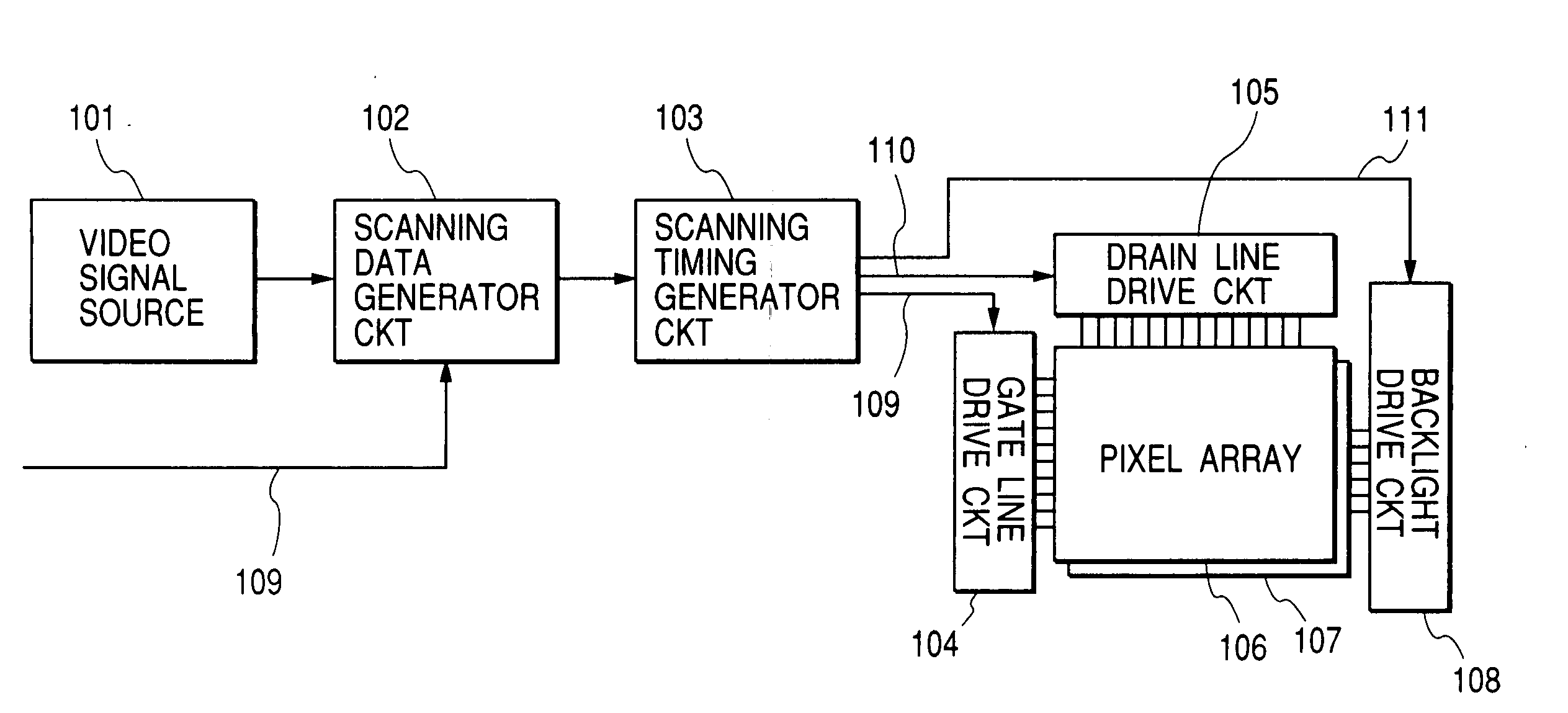
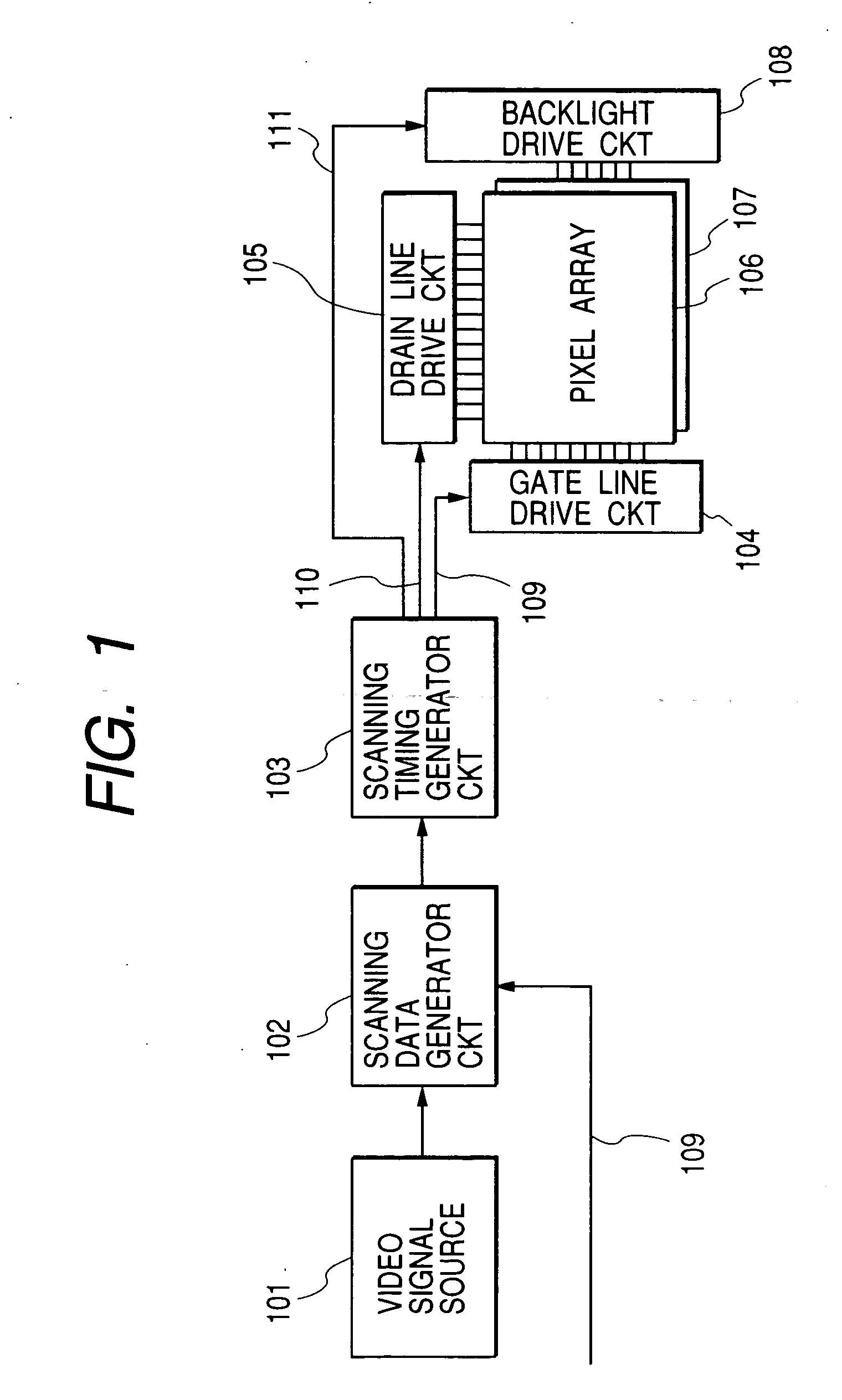
[0077]FIG. 1 is a block diagram showing a system provided with a liquid crystal display device in accordance with

[0078] This system is constructed as a part of a personal computer or a television set and includes not only a liquid crystal display device or a liquid crystal display module, but also includes a central processing unit (CPU) of the computer for transmitting video data to the liquid crystal display device or liquid crystal display module, a receiver of the television set, and a decoder of a digital versatile disc (DVD) and the like as a video signal source 101

[0079] The video data (video signal) generated by or reproduced by this video signal source 101 is received at an interface of the scanning data generator circuit 102, the format of the video data is converted and the picture of the liquid crystal display device is scanned a plurality of times to generate the video data suitable for reproduction. For example, the scanning data generator circuit 102 decomposes the da...

embodiment 2

[0236] Further, when a control for the backlight (light source device) described in the embodiment 2 is combined with a drive of the display device in accordance with the present embodiment or its application example, the moving image displayed by the present embodiment or its application example becomes clearer due to a blanking effect caused by blinking of the backlight. In addition, since the luminous efficacy of the light source device is also improved, displayed video quality of the display device (a liquid crystal display device) is also improved.

[0237] As already been described in reference to FIGS. 13B, 13C and FIGS. 14B, 14C of the embodiment 1, the present embodiment provides a description about a display device and its drive suitable for compensating for a difference between an aspect ratio of the pixel array and an aspect ratio of the video displayed by generating the effective display area displaying a video and an area (a surplus displaying area indicated in black) not...

embodiment 3

[0250] In this way, when the data transfer band in the drain line drive circuit is set to be sufficiently higher than the data transfer band corresponding to a resolution (the number of pixels) of the pixel array of XGA class having the drain line drive circuit installed therein, 576 gate lines arranged in the effective display area of the pixel array can be scanned by four times, for example, through the plural-line simultaneous write-in operation and the plural-line skip scanning operation in accordance with the embodiment 3 for every field period of 1080i data. Due to this fact, a blur of contour of a moving item displayed at a picture is restricted by displaying the video data corresponding to one field period of data of 1080i through front half twice scanning of four times scanning for the effective display area performed by the plural-line simultaneous write-in operation and the plural-line skip scanning, and by displaying the blanking data at the pixel array through rear half...


PUM

PropertyMeasurementUnit
frequencyaaaaaaaaaa
frequencyaaaaaaaaaa
transmission frequencyaaaaaaaaaa

Abstract

A display device which includes a plurality of adjacent gate lines and drain lines disposed in a display area of the display device, and a plurality of pixels disposed in the display area, each of the plurality of pixels having a switching element coupled to a corresponding one of the plurality of adjacent gate lines and a corresponding one of the plurality of drain lines. During one frame period, the plurality of adjacent gate lines are selected, and thereby video signals are written into the plurality of pixels via the plurality of drain lines, and thereafter during the one frame period, the plurality of adjacent gate lines are selected, and thereby signals corresponding to blanking data are written into the plurality of pixels.

Description

CROSS REFERENCE TO RELATED APPLICATION [0001] This application is a continuation of U.S. application Ser. No. 10 / 382,295, filed Mar. 7, 2003, the contents of which are incorporated herein by reference.BACKGROUND OF THE INVENTION [0002] This invention relates to a liquid crystal display device driven by a switching element using amorphous silicon, polycrystalline silicon or the like for each pixel, an electroluminescent-type display device, and a display device provided with a light emitting element such as a light emitting diode and the like for each pixel. In particular, this invention relates to a display device that performs blanking processing. [0003] Liquid crystal display devices have been widely used as display devices that retain light emitted from each of a plurality of pixels in a desired amount within a predetermined period of time (e.g., a period of time corresponding to 1 frame period) on the basis of video data inputted for each 1 frame period. In the liquid crystal di...

Claims


Application Information

Patent Timeline
Patent Type & Authority Applications(United States)
IPC IPC(8): G09F9/35G02F1/133G09G3/20G09G3/30G09G3/34G09G3/36G09G5/00G09G5/399H04N5/66
CPCG09G3/20G09G3/342G09G3/3648G09G5/399G09G2310/021G09G2340/0442G09G2310/0232G09G2320/0261G09G2320/062G09G2320/103G09G2340/0407G09G2310/0224
Inventor KAWABE, KAZUYOSHIHIRAKATA, JUNICHI
Owner PANASONIC LIQUID CRYSTAL DISPLAY CO LTD
Why Eureka
Try Eureka