Electronic control system having power source relay fusion detecting circuit

a technology of fusion detection and electronic control system, which is applied in the direction of relays, instruments, transportation and packaging, etc., can solve the problems of increasing part cost and manufacturing cost, and achieve the effect of small loss current and low cos

Inactive Publication Date: 2007-03-27
DENSO CORP
View PDF6 Cites 2 Cited by
  • Summary
  • Abstract
  • Description
  • Claims
  • Application Information

AI Technical Summary

Benefits of technology

[0011]The present invention has an object to provide an electronic control system, which can surely detect fusion of a power source relay in low cost and has small loss current. The present invention is particularly advantageous for a vehicle control system such as an electric power steering system, in which a large current of more than tens of amperes flows in the power source relay.
[0013]With the above construction, the charge accumulated in the capacitor is discharged by the two resistors. Therefore, the value of the current flowing in the first resistor is made smaller, and the heating quantity is also made smaller. Accordingly, the increase of temperature is small and thus resistors having small resistance to heat can be used, so that the part cost and the manufacturing cost can be reduced.

Problems solved by technology

This is, the parts to be used are restricted, resulting in increase of the part cost and the manufacturing cost.

Method used


Image

  • Electronic control system having power source relay fusion detecting circuit
  • Electronic control system having power source relay fusion detecting circuit
  • Electronic control system having power source relay fusion detecting circuit

Examples


first embodiment

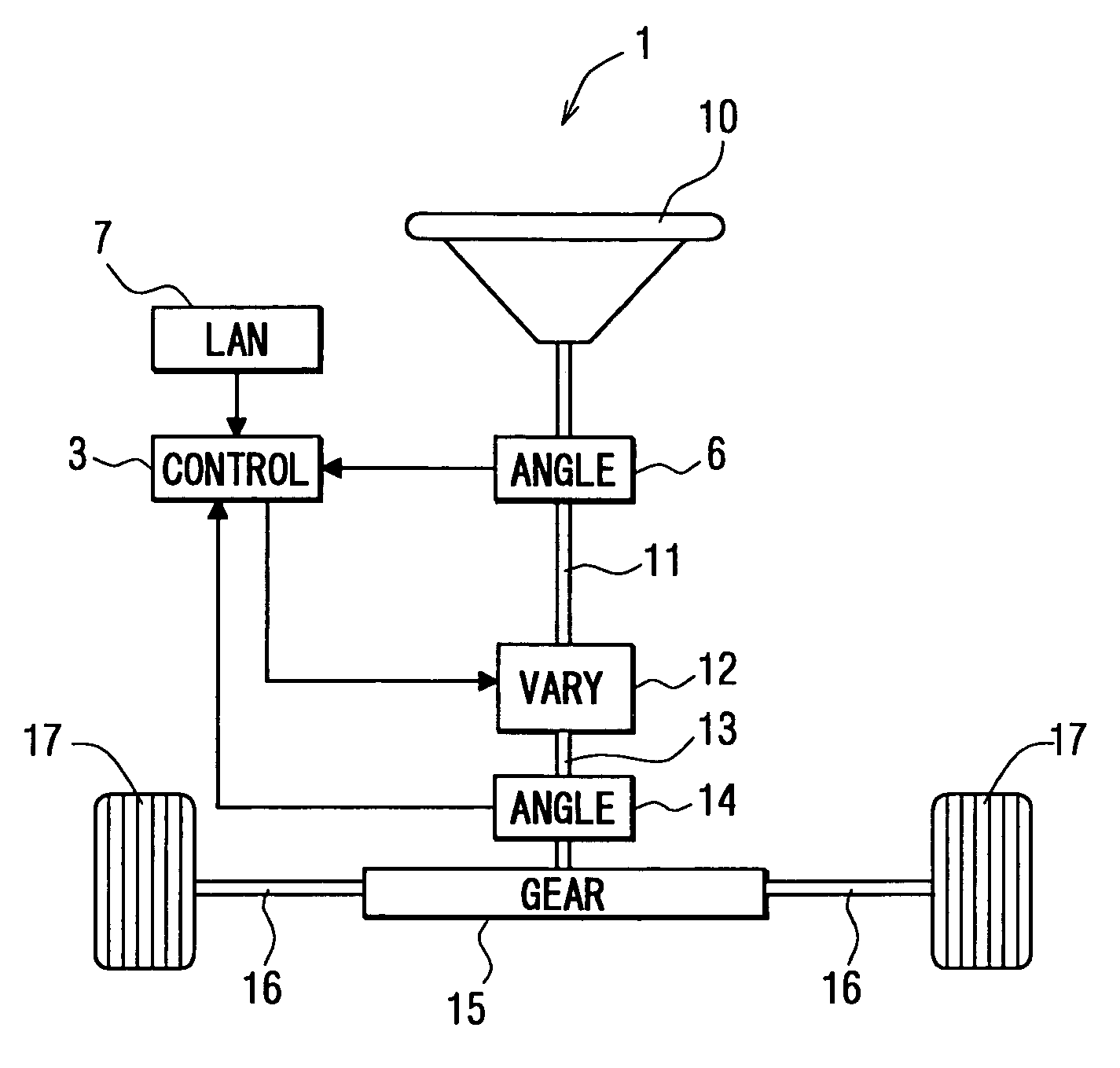
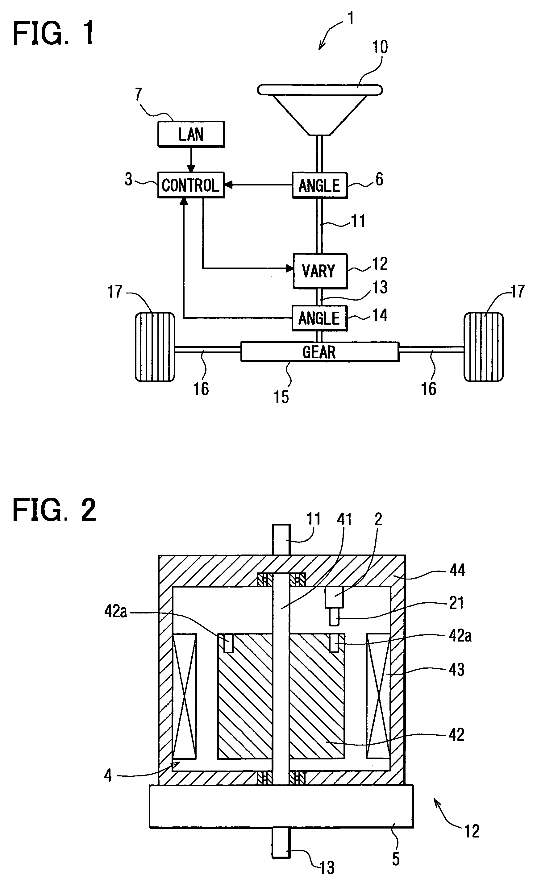
[0026]Referring first to FIG. 1, the electronic control system is a transfer-ratio varying steering system 1. A steering wheel 10 of a vehicle is connected to the upper end of an input shaft 11. The lower end of the input shaft 11 and the upper end of an output shaft 13 are connected to each other through a transfer-ratio varying mechanism 12. Furthermore, the lower end of the output shaft 13 is equipped with a pinion (not shown), and the pinion is engaged with a rack 16 in a steering gear box 15. Furthermore, an electromotive power steering device (not shown) is equipped in the steering gear box 15. Steered tire wheels 17 are connected to both ends of the rack 16 through tie rods and arms (not shown).

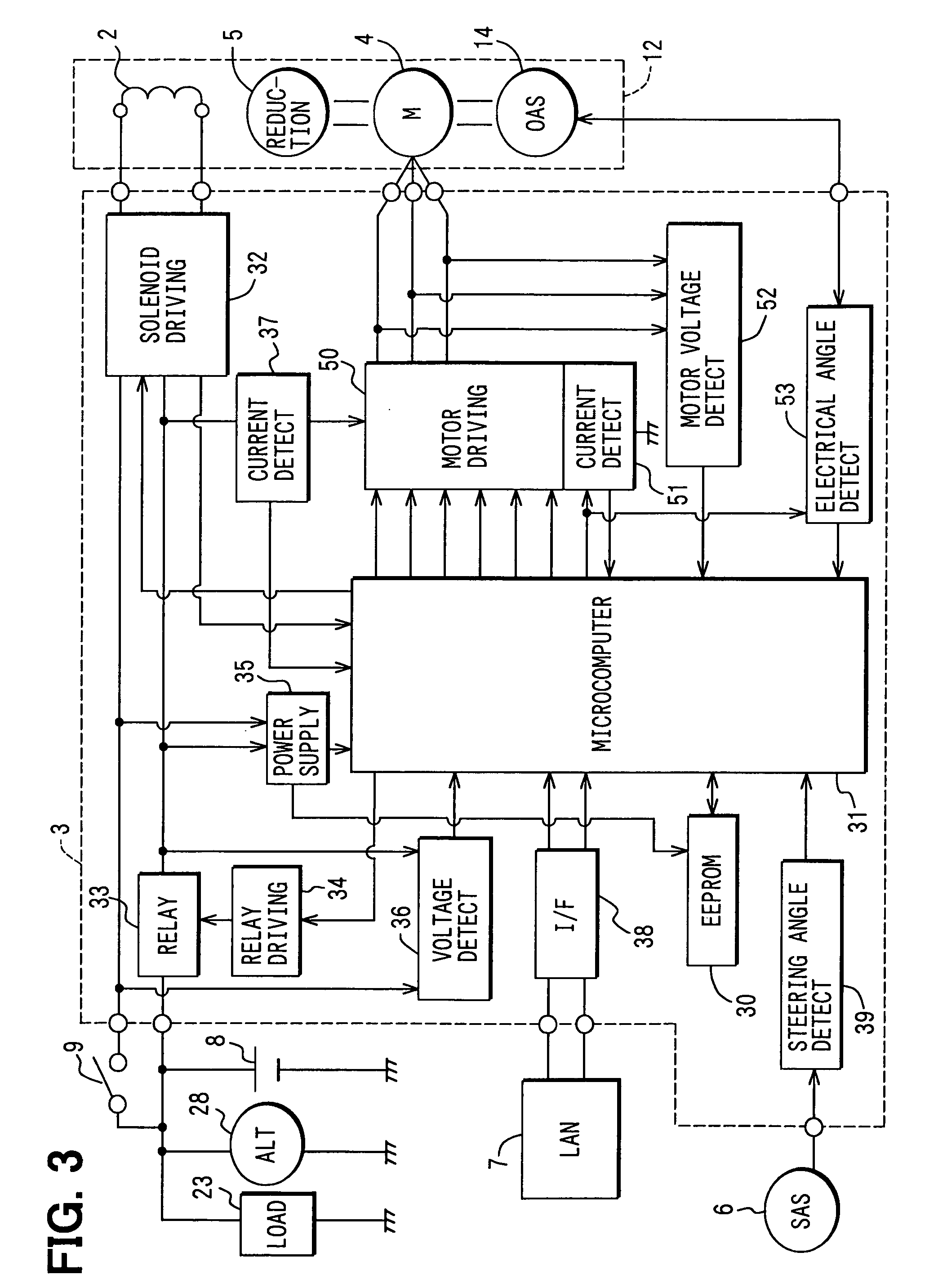
[0027]The input shaft 11 is equipped with a steering angle sensor 6 for detecting the steering angle of the steering wheel 10. The output shaft 13 is equipped with an output angle sensor 14 including a resolver for detecting the turning angle of the steered wheels 17. The output angle ...

second embodiment

[0057]A second embodiment is shown in FIG. 6. A transistor T701 is connected between a resistor R204 of the motor driving circuit 50 (FIG. 3) and the ground, and the output terminal of the microcomputer 31 and the base terminal of the transistor T701 are connected to each other through a resistor R702.

[0058]When the power relay 33 is set to the ON-state, a control instruction is transmitted as a PWM signal from the microcomputer 31 to the transistor T701, and the transistor T701 is subjected to duty operation. The microcomputer 31 outputs to the relay driving circuit 34 an instruction for setting the power source relay 33 from the ON-state to the OFF-state, and also outputs to the transistor T701 a signal for setting the duty ratio for driving the transistor T701 to 100%, whereby the transistor T701 is set to the ON-state at all times and a discharge path extending from the resistor R204 through the transistor T701 to the ground is formed, so that the charge accumulated in the capac...

third embodiment

[0061]A third embodiment is shown in FIG. 7. The motor driving circuit 50 is wired to form a well-known three-phase bridge circuit. The circuit 50 includes fly-wheel diodes forming a bypass path of induced current caused by the switching of three-phase coils of U, V, W of the motor 4. If switching elements 301 to 306 are subjected to switching operation by using the rotational angle signal from the output angle sensor 14 and the PWM signal from a driving IC 314 which is based on an instruction from the microcomputer 31, a coil whose phase is associated with current supply can be selectively subjected to PWM current supply.

[0062]The switching elements 301, 302, 303 carry out switching operations of U-phase, V-phase and W-phase, respectively. Those switching elements are used as upper arm side switching elements. Furthermore, the switching elements 304, 305, 306 carry out the switching operations of U-phase, V-phase and W-phase, respectively. Those switching elements are used as lower...


PUM


Abstract

An electronic control system comprises a power source, a controller and a power source relay for supplying and cutting off a supply of power to the controller. A fusion detecting circuit includes a capacitor and a first resistor connected to the power source relay to detect fusion of the power source relay. A second resistor is connected in parallel to the first resistor. A switching element is connected to one of the first resistor and the second resistor in series. The switching element is set to an ON-state when the power source relay is set to the OFF-state, thereby discharging a charge accumulated in the capacitor through the first resistor and the second resistor.

Description

CROSS REFERENCE TO RELATED APPLICATION[0001]This application is based on and incorporates herein by reference Japanese Patent Applications No. 2004-21544 filed Jan. 29, 2004 and No. 2004-281579 filed Sep. 28, 2004.FIELD OF THE INVENTION[0002]The present invention relates to an electronic control system having a fusion detecting circuit for a power source relay.BACKGROUND OF THE INVENTION[0003]In many electronic control systems, a power source relay is used to control a power supply to an electronic controller, actuators and the like. The power source relay may sometimes be held fixed to any one of the ON-state and the OFF-state contrary to the instruction from an external instruction signal to change the ON / OFF state. For instance, a movable contact is held inseparably fused to a fixed contact, and is uncontrollable to the other state. It is necessary to detect fusion (welding) of the power source relay. One example of such a fusion detecting circuit is disclosed in JP 2004-32903A.[...

Claims


Application Information

Patent Timeline
Patent Type & Authority Patents(United States)
IPC IPC(8): H01H9/00H01H47/00H01H51/22H01H51/30B62D6/00B62D5/00B62D5/04B62D101/00B62D113/00B62D119/00
CPCB62D5/008H01H47/002B62D5/0484G01R31/3278
Inventor ITO, YOSHIHIROTSUTSUI, TOSHIO
Owner DENSO CORP
Why Eureka
Try Eureka