

Polar modulation transmission apparatus and radio communication apparatus
a radio communication apparatus and modulation technology, applied in modulation, digital transmission, pulse technique, etc., can solve the problems of inability to correct, inability to suppress the deterioration of transmission quality, no other way to adjust synchronization, etc., to achieve simple configuration accurately and automatically.
- Summary
- Abstract
- Description
- Claims
- Application Information
AI Technical Summary
Benefits of technology
Problems solved by technology
Method used
Image

Examples
Embodiment Construction
[0039] With reference now to the attached drawings, embodiments of the present invention will be explained in detail below.
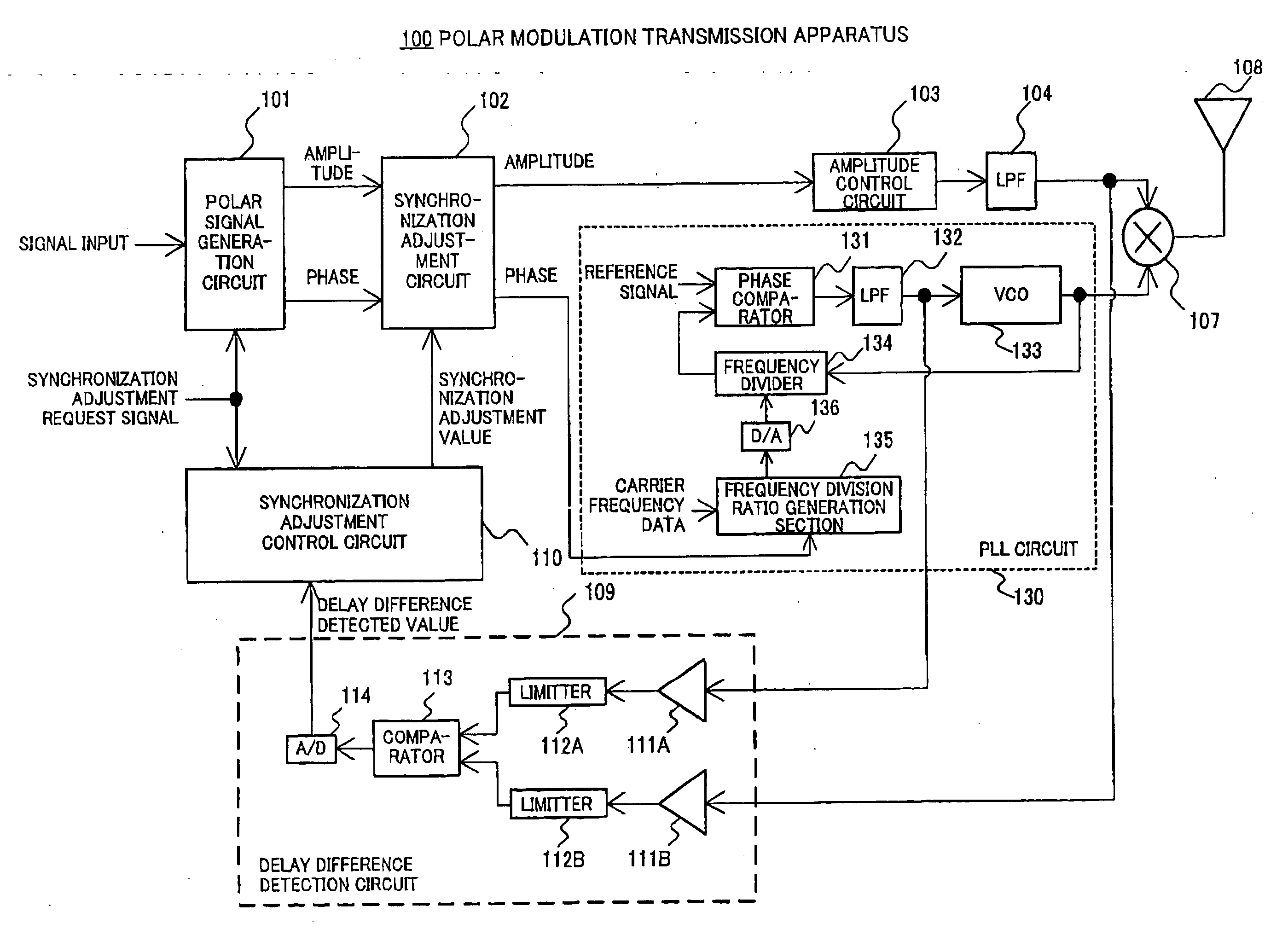
[0040]FIG. 5 shows the configuration of a polar modulation transmission apparatus according to embodiment 1 of the present invention. The polar modulation transmission apparatus 100 is mounted on a radio communication apparatus such as a portable terminal and its base station apparatus.
[0041] The polar modulation transmission apparatus 100 inputs a baseband modulated signal to a polar signal generation circuit 101. The polar signal generation circuit 101 separates the baseband modulated signal into an amplitude signal made up of an amplitude component and a phase signal made up of a phase component. Furthermore, the polar signal generation circuit 101 receives a synchronization adjustment request signal and generates an amplitude signal and a phase signal for synchronization adjustment when this synchronization adjustment request signal requests synchronizatio...
PUM
 Abstract
Description
Claims
Application Information