Generator

a generator and generator technology, applied in the field of generators, can solve problems such as difficult to find abnormalities, and achieve the effects of reducing target voltage, ensuring reliability, and protecting the generator with ease and reliability

Active Publication Date: 2005-12-01
HONDA MOTOR CO LTD
View PDF8 Cites 17 Cited by
  • Summary
  • Abstract
  • Description
  • Claims
  • Application Information

AI Technical Summary

Benefits of technology

[0010] According to the first characteristic, when the added up value of the output powers of a plurality of independent rectifier circuits becomes a predetermined power, it is considered that a more increase in the added up value of the output current as over-power and hence a target voltage is reduced. Because the rectifier circuits are controlled such that the output voltage become a target voltage, the output voltages of the rectifier circuits are reduced with reduction of the target voltage, whereby the upper limit of the output power can be kept at a predetermined value. Therefore, it is possible to protect the generator with ease and with reliability even in an overload range where a large load current is required.
[0011] According to the second characteristic, even in the event that a load such as a battery is connected in reverse polarity to an output

Problems solved by technology

Hence, there is presented a problem that when an abnormality occurs in any one of the plurality of power supply units

Method used


Image

  • Generator
  • Generator
  • Generator

Examples


Embodiment Construction

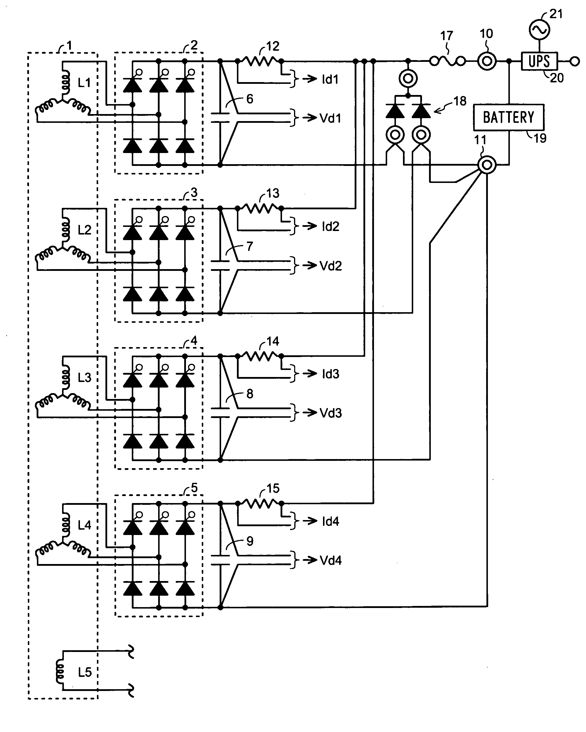
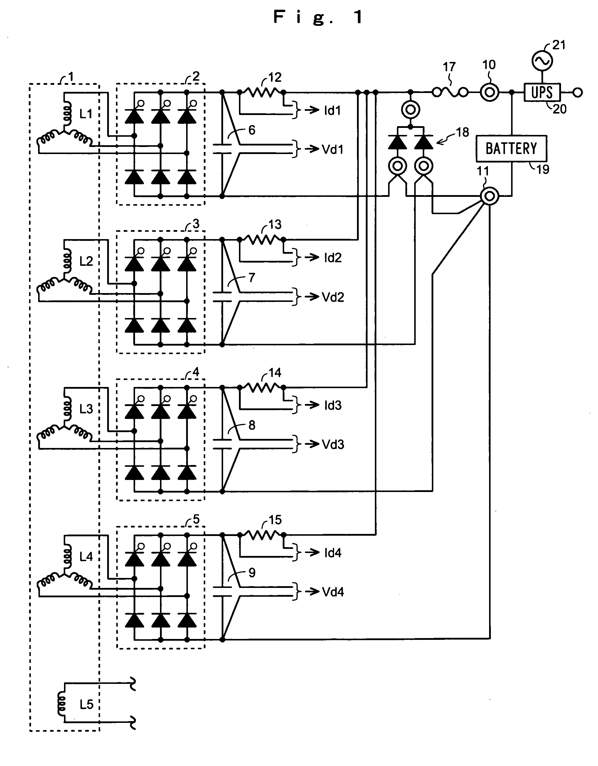
[0018] An embodiment of the present invention will be described below in detail with reference to the drawings. FIG. 1 is a construction diagram of the main portion of a portable generator in accordance with an embodiment of the present invention. In FIG. 1, the stator 1 of a generator body consists of four output windings L1, L2, L3, and L4 those are independent of each other and an auxiliary winding L5 independent of these output windings L1 to L4, wherein the four output windings L1, L2, L3, and L4 and the auxiliary winding L5 are wound around the protruding poles of a single stator iron core (not shown). The output windings L1 to L4 are equal to each other in the number of windings and in the diameter of the wire, that is, identical in specifications.

[0019] The stator 1 is disposed in the center of the generator body and a rotor having a plurality of magnets disposed annularly, that is, an outer rotor is commonly arranged on the outer periphery of the stator 1. The rotor is con...


PUM


Abstract

An abnormality of a generator provided with a plurality of power supply units is easily detected. Each of the power supply units includes each of output windings L1 to L4, which are wound independently of each other around the single iron core, and each of rectifier circuits 2 to 5. The power supply units produce an integrated output power. Control means 33 to 35 control the rectifier circuits such that an output voltage agrees with a target voltage Vref. In a case where an added up power W becomes a power target value Wref, when the added up current I further increases, a power comparing section 39 reduces the target voltage Vref to prevent the rectifier circuits from outputting power. Further, when the added up current I exceeds a current upper limit ILMT, a gate pulse is stopped.

Description

BACKGROUND OF THE INVENTION [0001] 1. Field of the Invention [0002] The present invention relates to a generator and, in particular, to a generator capable of outputting a comparatively large direct current and being appropriately protected in an overload range. [0003] 2. Description of the Related Art [0004] A generator driven by an engine or the like has been conventionally widely employed as the power supply of an electric appliance especially used for outdoor works and for leisure-time activities. Further, in recent years, the uses of the generator are spreading also to the back-up power supply, that is, the so-called uniterruptible power supply (UPS) for computers and the like. When the generator of this kind is constructed as a generator for outputting a direct current, there is a tendency that the generator is required to be small in size and to be able to output a comparatively low voltage and a large current. In the generator required to output a large current like this, a ...

Claims


Application Information

Patent Timeline
IPC IPC(8): H02H7/06H02M3/335H02M7/08H02P9/00H02M7/12H02P11/00
CPCH02P9/006H02M7/08
Inventor NAKAGAWA, YOSHINORIINOUE, TOSHIOMURONOI, KAZUFUMI
Owner HONDA MOTOR CO LTD
Why Eureka
Try Eureka