A charge pump circuit

A technology of charge pump and circuit, applied in the direction of conversion equipment without intermediate conversion to AC, can solve the problem of high cost

Active Publication Date: 2015-12-09
WUXI ZGMICRO ELECTRONICS CO LTD
View PDF6 Cites 0 Cited by
  • Summary
  • Abstract
  • Description
  • Claims
  • Application Information

AI Technical Summary

Problems solved by technology

[0005] In order to solve the technical problem of high cost due to the need for more flying capacitors in the prior art in order to obtain more rate modes

Method used


Image

  • A charge pump circuit
  • A charge pump circuit
  • A charge pump circuit

Examples


Embodiment Construction

[0035] The specific embodiments of the present invention will be described in detail below in conjunction with the accompanying drawings. It should be noted that these specific descriptions are only for those of ordinary skill in the art to understand the present invention more easily and clearly, rather than limiting interpretation of the present invention.

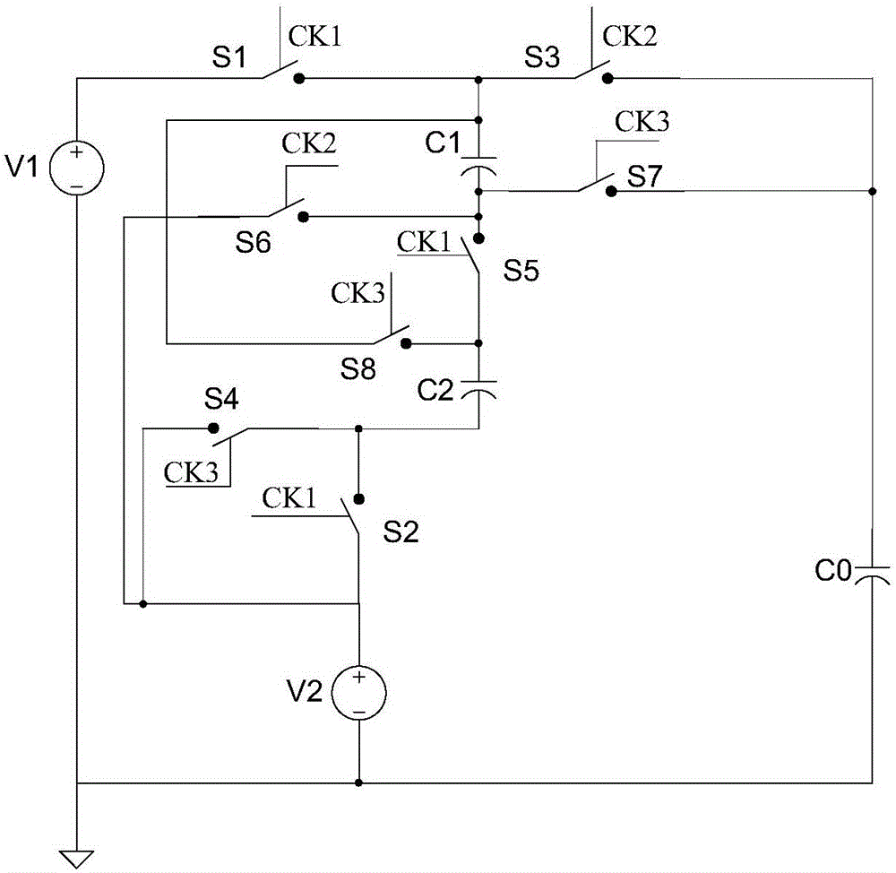
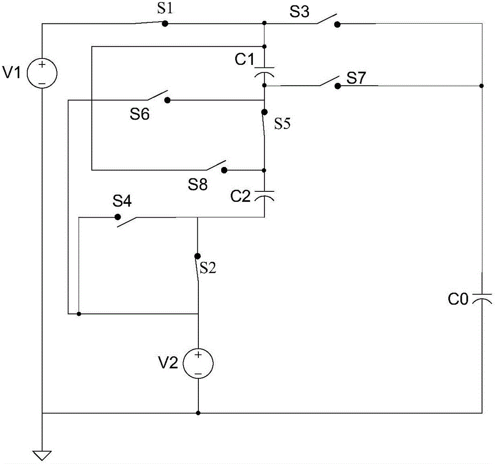
[0036] Such as figure 1 Shown is the structural diagram of the charge pump circuit provided by the present invention. The charge pump circuit provided by the invention includes: two power supplies, eight switches, three capacitors and three clock signals. specifically:

[0037] The charge pump circuit includes: a first input power supply V1; a first capacitor C1; a second capacitor C2; an output capacitor C0; it is characterized in that it also includes:

[0038] The second input power supply V2, one end of which is connected to an equipotential point with one end of the first input power supply V1, and one end of the ...


PUM


Abstract

The invention provides a circuit of a charge pump. The circuit of the charge pump comprises a first input power source, a first capacitor, a second capacitor and an output capacitor. The circuit of the charge pump is characterized by further comprising a second input power source, eight control switches and three clock signals used for having control over the control switches, and finally, obtained output voltage v0 can be obtained through the two input power sources and control of the eight control switches according to the formula v0=1 / 3*v1+2 / 3*v2. Due to the facts that specific scaling factors can be formed through electronic components, the scaling factors are multiplied by the input power sources, and then summation is carried out, even when the capacitors are limited in number, multiple multiplying-power output can be formed.

Description

technical field [0001] The invention relates to the technical field of voltage conversion, in particular to a charge pump circuit. Background technique [0002] There are two common charge pumps in the prior art: one is used in a phase-locked loop circuit and is connected to the rear stage of a frequency and phase detector to generate a relatively stable voltage by charging and discharging a capacitor for use in Control the frequency of the voltage-controlled oscillator; the other is through the switch capacitor, which is used for voltage conversion and can provide a power output circuit with a large output current. Because this charge pump can achieve high voltage conversion efficiency, it is based on the switch capacitor The charge circuit is widely used in voltage conversion circuits. In order to distinguish the two, the latter is called a power charge pump. A general power charge pump adopts an input voltage and can generate an output voltage higher than the input volt...

Claims


Application Information

Patent Timeline
Patent Type & Authority Patents(China)
IPC IPC(8): H02M3/07
Inventor 王钊
Owner WUXI ZGMICRO ELECTRONICS CO LTD
Why Eureka
Try Eureka