
Engine mounting stand

a technology for mounting stands and engines, which is applied in the direction of machine supports, manufacturing tools, other domestic objects, etc., can solve the problems of affecting the use of engines

Inactive Publication Date: 2005-12-15
KINCAID MICHAEL C
View PDF4 Cites 16 Cited by
  • Summary
  • Abstract
  • Description
  • Claims
  • Application Information

AI Technical Summary

Benefits of technology

[0009] The present invention is an engine mounting stand for small engines, and is particularly adapted for motorcycle engines. The stand includes an upright with a journal bearing, an adjustable bracket fixture, an outrigger support and outrigger. The present invention provides a means for the mechanic to comfortably work on the engine and access all areas of the engine.

Problems solved by technology

One problem in repair or modifying engines is gaining access to various components of the engine.
This method forces the mechanic to work in an uncomfortable position, and inhibits access to many parts of the engine.
In this case, the engine is then generally simply laid on a workspace, such as a work bench where it is subject to undesirable movement when sufficient force is applied.
The engine may be bolted into a stationary mounting frame known in the art however, access to many parts of the engine remain inhibited.

Method used


Image

  • Engine mounting stand
  • Engine mounting stand
  • Engine mounting stand

Examples


Embodiment Construction

[0015] In accordance with the present invention, an engine mounting stand is disclosed. The present invention relates to an engine mounting stand for small engines, and particularly adapted for motorcycle engines. The present invention allows the mechanic access to all areas of the engine. In the broadest context, the present invention consists of components configured and correlated with respect to each other so as to attain the desired objective.

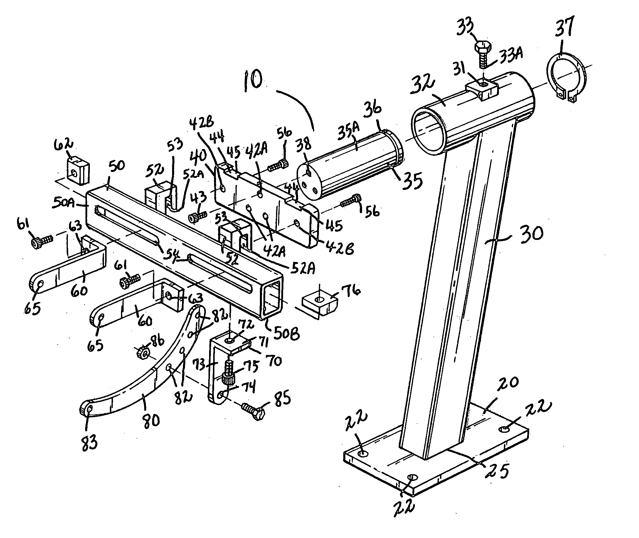
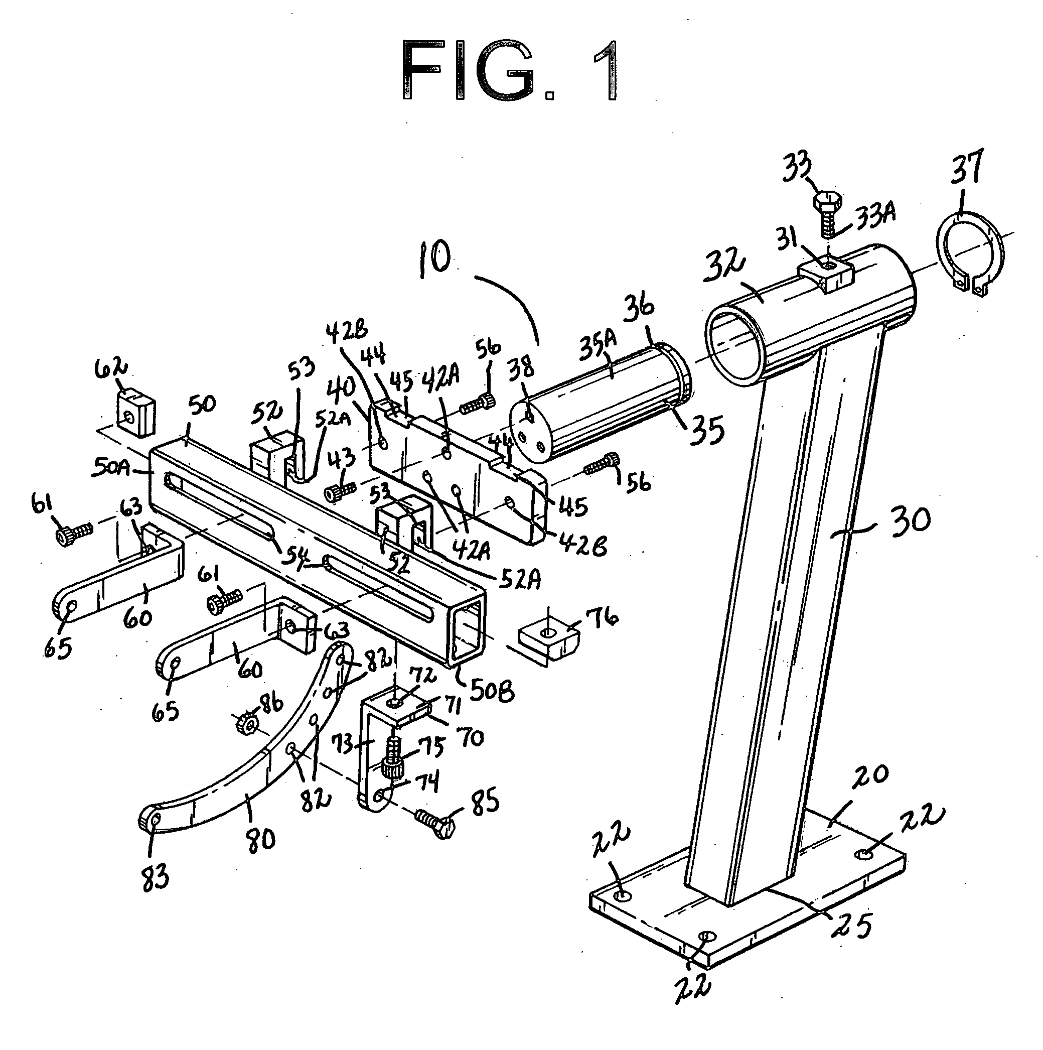
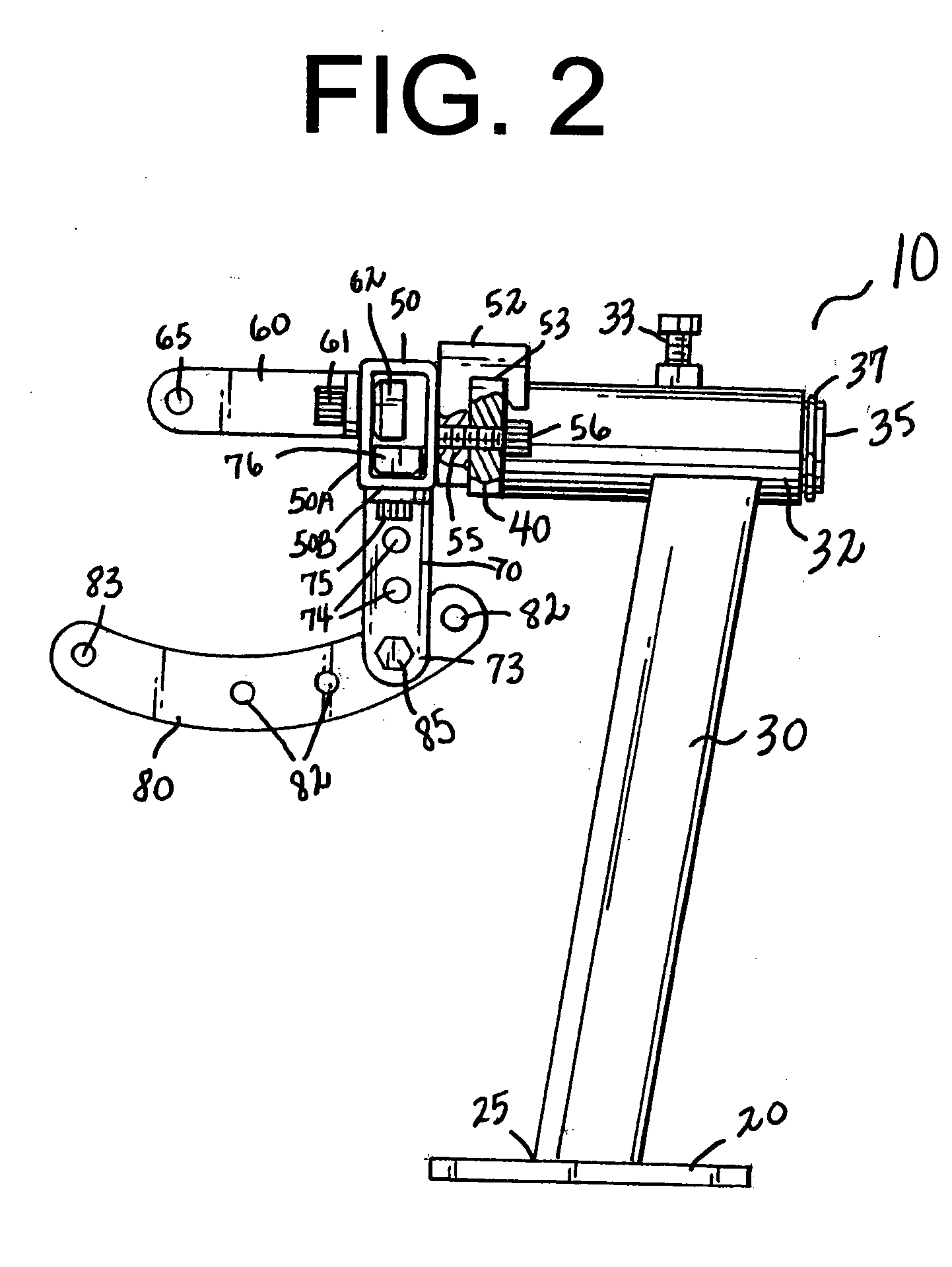
[0016]FIGS. 1-4 illustrate the preferred embodiment of an engine mounting stand 10 made in accordance with the present invention. The engine mounting stand 10 includes a vertical upright 30 having a journal bearing 35 mounted in a tubular sleeve 32 integral to the upright 30 so that, as will be further discussed, rotation of journal bearing 35 is smooth and properly supported.

[0017] As best shown in FIG. 1, the journal bearing 35 includes a slot 36 sized to receive a lock ring 37 for removably maintaining the journal bearing 35 within th...


PUM


Abstract

An engine mounting stand for small engines, and particularly adapted for motorcycle engines. The engine mounting stand includes an upright and a journal bearing, the upright is attached to a base, a rotating bracket assembly is attached to the journal bearing of the upright, the bracket assembly designed to attach to the engine mount holes of the engine, and is operative for rotatably positioning the engine so that the mechanic can access all areas of the engine. The engine mounting stand can further include an outrigger support attached to the rotating bracket assembly, and an outrigger secured to the outrigger support. The outrigger attaches to the engine and outrigger end aperture can provide further attachment support to the bracket assembly.

Description

CROSS REFERENCES TO RELATED APPLICATIONS [0001] U.S. Provisional Application for Patent No. 60 / 578,386, filed Jun. 10, 2004, with title “Engine Mounting Stand” which is hereby incorporated by reference. Applicant claims priority pursuant to 35 U.S.C. Par. 119(e)(i). [0002] Statement as to rights to inventions made under federally sponsored research and development: Not ApplicableBACKGROUND OF THE INVENTION [0003] 1. Field of the Invention [0004] The present invention relates generally to engine stands, and more particularly to an engine mounting stand such as, but not restricted to a motorcycle engine mounting stand. [0005] 2. Brief Description of Prior Art [0006] One problem in repair or modifying engines is gaining access to various components of the engine. Typically, people working on small engines such as a motorcycle engine simply leaves the engine mounted in the motorcycle frame. This method forces the mechanic to work in an uncomfortable position, and inhibits access to many...

Claims


Application Information

Patent Timeline
IPC IPC(8): F16M1/00B25H1/00
CPCB25H1/0007
Inventor KINCAID, MICHAEL C.
Owner KINCAID MICHAEL C
Learn More