Electronic apparatus and magnetic lock device thereof

Inactive Publication Date: 2006-01-12
ASUSTEK COMPUTER INC
View PDF3 Cites 97 Cited by
  • Summary
  • Abstract
  • Description
  • Claims
  • Application Information

AI Technical Summary

Benefits of technology

[0012] As mentioned above, the electronic apparatus and the magnetic lock device thereof of the invention utilize the polarities or locations changing between the first magnetic element and the second magnetic element as well as working on the principle of unlike poles attract. Thus, the first body and the second body that this magnetic lock device is set in are closed be

Problems solved by technology

However, since the notebook tends toward more thin design, users are still difficult to open it, even the hook 42 is d

Method used


Image

  • Electronic apparatus and magnetic lock device thereof
  • Electronic apparatus and magnetic lock device thereof
  • Electronic apparatus and magnetic lock device thereof

Examples


Example

[0020] The present invention will be apparent from the following detailed description, which proceeds with reference to the accompanying drawings, wherein the same references relate to the same elements.

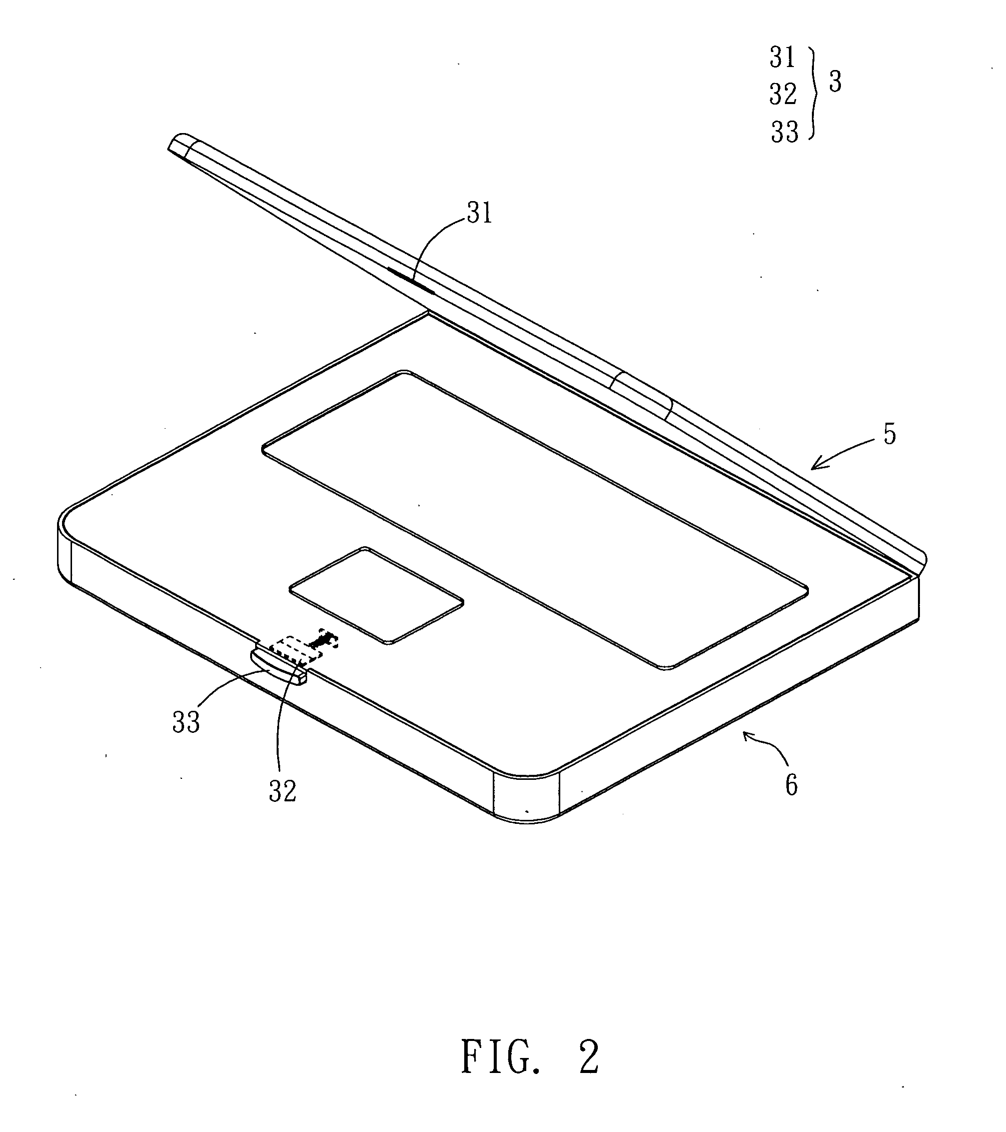
[0021] With reference to FIG. 2, the magnetic lock device 3 according to the embodiment of the invention is separately located on a first body 5 and a second body 6. The magnetic lock device 3 comprises a first magnetic element 31, a second magnetic element 32, and a control module 33. The first body 5 is a monitor while the second body 6 is a host. Certainly, the first body5 also can be a host while the second body 6 is a monitor.

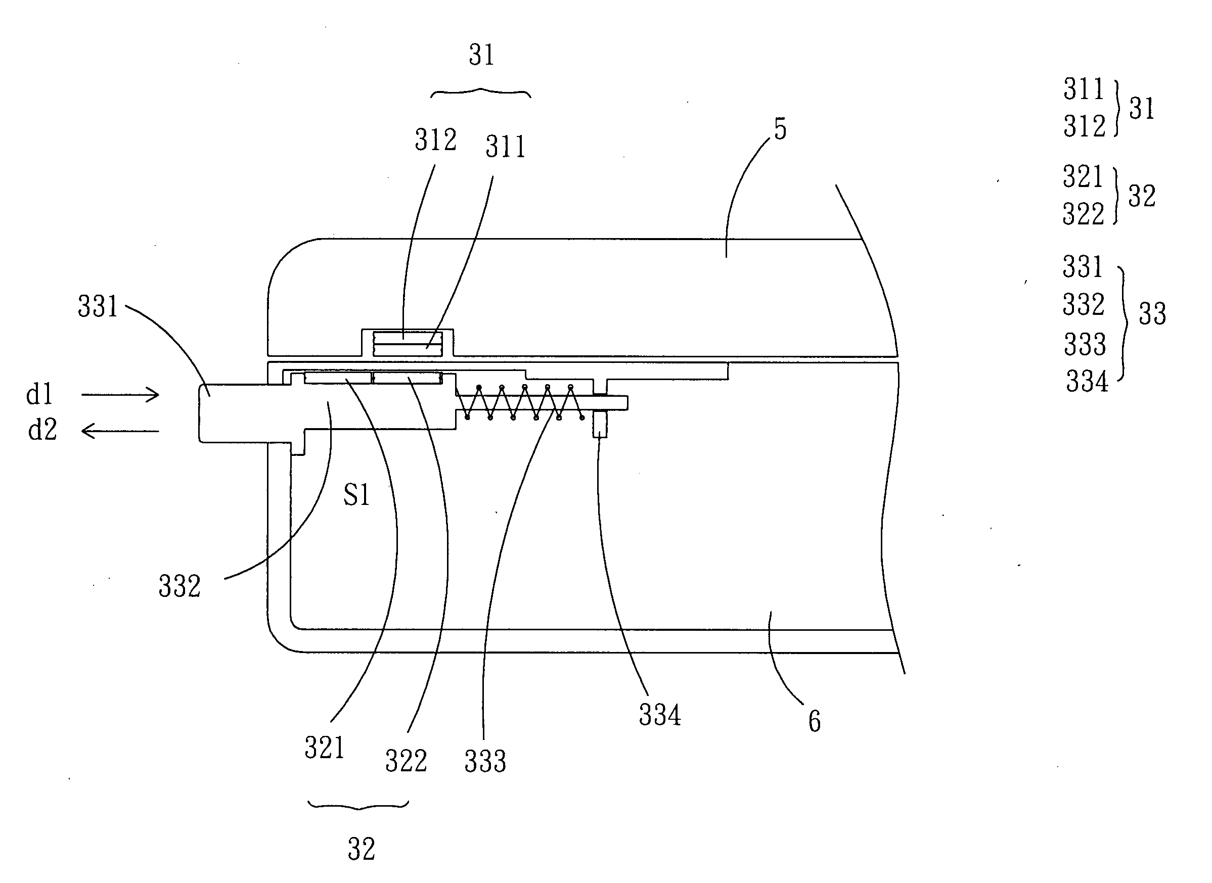
[0022] In the present embodiment, as is shown in FIG. 3, the first magnetic element 31, which is located on the first body 5, comprises a first part 311 and a second part 312. The first part 311 has a first polarity and the second part 312 has a second polarity. The second magnetic element 32, which is located on the second body 6, comprises a third part ...


PUM


Abstract

A magnetic lock device is separately located on a first body and a second body, which are pivoted with each other. The magnetic lock device comprises a first magnetic element, a second magnetic element, and a control module. The first magnetic element located on the first body comprises a first part and a second part. The first part has a first polarity and the second part has a second polarity. The second magnetic element located on the second body comprises a third part and a fourth part. The polarity of the third part is the first polarity and the polarity of the fourth part is the second polarity. The second polarity is opposite to the first polarity. When the first body and the second body are closed, the first part faces to the fourth part for providing a magnetic attraction between the first body and the second body. The control module is located on the second body. When the control module is triggered, the first part faces to the third part for providing a magnetic repulsion between the first body and the second body.

Description

BACKGROUND OF THE INVENTION [0001] 1. Field of Invention [0002] The invention relates to an electronic apparatus and lock device thereof and, in particular, to an electronic apparatus and magnetic lock device thereof. [0003] 2. Related Art [0004] With the coming of the electronic times, the dependence and need of electronic products for people are increasing. In addition, the technology changes with each passing day, so consumers determine whether a product to be bought not only with considering the product's price but also considering the features and friendly use of the product. Therefore, the manufacturers of the electronic products always make the effort to think about how to fit the requirements of consumers. [0005] For understanding the present invention easily, herein the notebook is taken as an example. With reference to FIG. 1, a conventional notebook comprises a monitor 1 and a host 2, which is pivoted on the monitor 1. The screen 12 of the monitor 1 faces to the host 2 an...

Claims


Application Information

Patent Timeline
IPC IPC(8): E05C17/56
CPCE05C19/16G06F1/1679G06F1/1616Y10T292/11
Inventor KANG, LUNWEIHO, CHICHUNG
Owner ASUSTEK COMPUTER INC
Why Eureka
Try Eureka