Table support structure

a support structure and table technology, applied in the field of tables, can solve the problems of unsatisfactory use, unsatisfactory use, and difficulty in moving two bar linkage systems into locking positions, and achieve the effects of avoiding unsatisfactory use, avoiding unsatisfactory use, and avoiding unsatisfactory us

Inactive Publication Date: 2006-02-02
RUBBERMAID HOME PROD
View PDF41 Cites 39 Cited by
  • Summary
  • Abstract
  • Description
  • Claims
  • Application Information

AI Technical Summary

Problems solved by technology

At least some known tables are cumbersome to use.
For example, some two bar linkage systems may ...

Method used


Image

  • Table support structure
  • Table support structure
  • Table support structure

Examples


Embodiment Construction

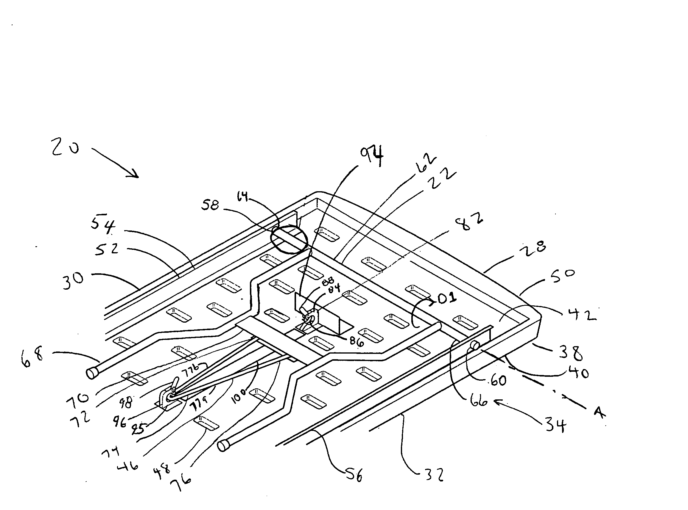
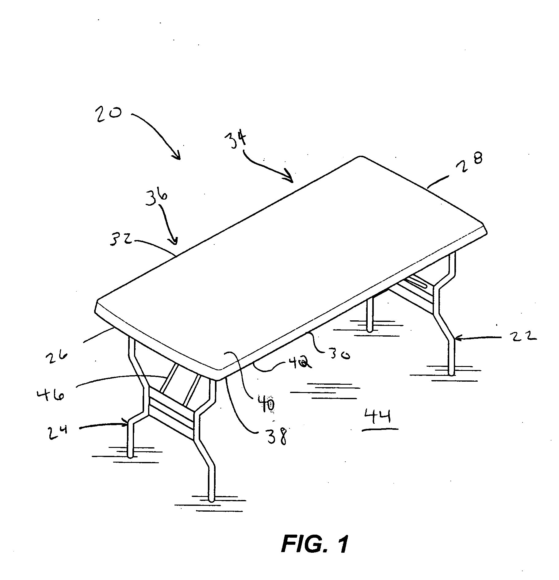
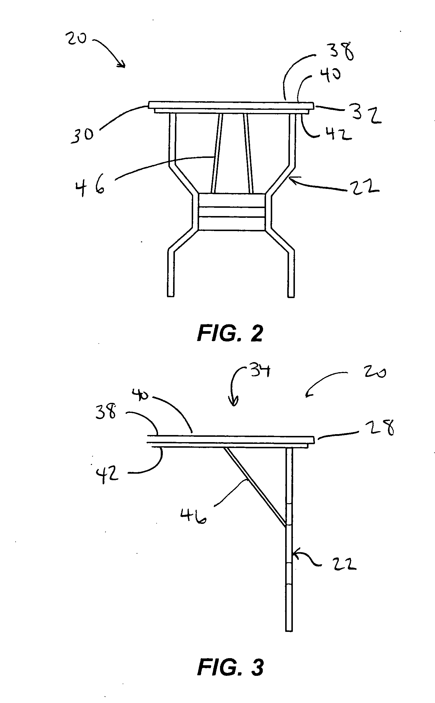
[0019] Referring now to the drawings, FIGS. 1-3 depict a first example of a table 20 with a first foldable support 22. In this example, the table 20 also includes a second foldable support 24. The table 20 defines a left side 26, a right side 28, a front side 30 and a back side 32. The table 20 further defines a right half 34 and a left half 36. The first support 22 is located near the right side 28, and the second support 24 is located near the left side 26. The table 20 includes a table top 38 with a top side 40 and an underside 42. In this example, only the first support 22 will be described, as it will be understood that the structure on the left half 36 of the table 20, including the second support 24, can be a mirror image of the structure on the right half 34. All directional labels of the table 20, e.g. front, left, top sides, etc., are for reference and convenience of description only, and not intended to limit the table 20 in any way.

[0020] The first support 22 and second...


PUM


Abstract

A table includes a table top with an underside. A support is rotatably connected to the underside of the table top and is rotatable at least between a stored position lying generally adjacent the underside and an extended position in which the support extends generally away from the underside. A bearing brace is hingedly attached to the support at a joint and includes a first end distal from the joint. A set-up latch is on the underside of the table top, with the first end of the bearing brace being releasably securable in the set-up latch when the support is in the extended position.

Description

FIELD OF THE INVENTION [0001] The invention relates to tables, and more particularly to tables with support legs that fold for easy storage. BACKGROUND OF THE INVENTION [0002] Folding tables such as banquet tables have a table top and a support on each end attached to the underside of the table top. Each support can include a pair of legs and can be collapsible or can fold between an extended position and a stored position. In the extended position, the supports are approximately perpendicular to the table top, while in the stored position, the supports are folded against the table top. By placing the supports in the stored position, the table can be stored in a comparatively small space. [0003] In a particular known table, each support is rotatably attached to the underside of the table top. A two bar linkage has a first end connected to the underside of the table top and a second end connected to the support at a position approximately midway down the support. As the support is ro...

Claims


Application Information

Patent Timeline
IPC IPC(8): A47B3/00
CPCA47B3/0918
Inventor PLEIMAN, BRIAN R.SANDER, DAVID R.FLOYD, GREGORY S.
Owner RUBBERMAID HOME PROD
Why Eureka
Try Eureka