Large size image projection

a projection system and image technology, applied in the field of two-dimensional projection, can solve the problems of limited size, insufficient power of single-mode lasers to produce color images of uniform brightness, and limited resolution of known image projection systems, so as to prevent any undesirable seams, reduce the intensity of selected pixels, and eliminate uneven brightness across the image

Inactive Publication Date: 2006-04-27
MICROVISION
View PDF22 Cites 24 Cited by
  • Summary
  • Abstract
  • Description
  • Claims
  • Application Information

AI Technical Summary

Benefits of technology

[0007] Still another object of this invention is to reduce speckle noise in image projection systems.
[0008] Yet another object of this invention is to create realistic three-dimensional color images.
[0009] An additional object is to eliminate cross-coupling between identical drive and pick-up mechanisms used to project images in such projection systems. FEATURES OF THE INVENTION
[0011] In accordance with one aspect of this invention, the image produced from each pattern is larger in size than the image produced by any one of the patterns. The overlap region prevents any undesirable seams from marring an observer's view of the image. By reducing the intensity of the selected pixels in the overlap region, bright spots and uneven brightness across the image are eliminated.
[0014] Still another feature resides in reducing speckle noise by producing a plurality of reflections at each pixel. In the case of a front projection screen, it can be constituted of a slightly transmissive material to produce the multiple reflections. In the case of a rear projection screen, the thickness and optical transmission characteristic of the screen are factors that control the multiple reflections. Speckle noise can also be reduced by using multiple lasers with the same wavelength.
[0017] Still another feature is embodied in minimizing cross-coupled signals in image projection arrangements. For example, if a piezoelectric drive mechanism is used to oscillate a scan mirror, and if an identical piezoelectric pick-up mechanism is used to generate a feedback signal indicative of the position of the oscillating mirror, then mechanical vibrations induced by the drive mechanism interferes with the pick-up mechanism and, as a result, a clean feedback signal is not generated, thereby ruining high quality image projection.

Problems solved by technology

However, the known image projection systems project an image of limited resolution, typically less than a fourth of video-graphics-array (VGA) quality of 640×480 pixels, and of limited size.
In the case of a color image formed by laser beams of different wavelengths (colors), some laser sources, for example, red semiconductor single mode lasers have insufficient power to produce a color image of uniform brightness.
The use of multimode red lasers having higher power is however restricted by their highly divergent laser beams.
Speckle noise, which is caused by the coherent nature of laser light, is an omnipresent problem that detracts from good display quality.
The known projected images are two-dimensional, which lacks the greater realism of a three-dimensional display.
These identical mechanisms result in cross-coupled signals which lead to noise and distortion.

Method used


Image

  • Large size image projection
  • Large size image projection
  • Large size image projection

Examples


Embodiment Construction

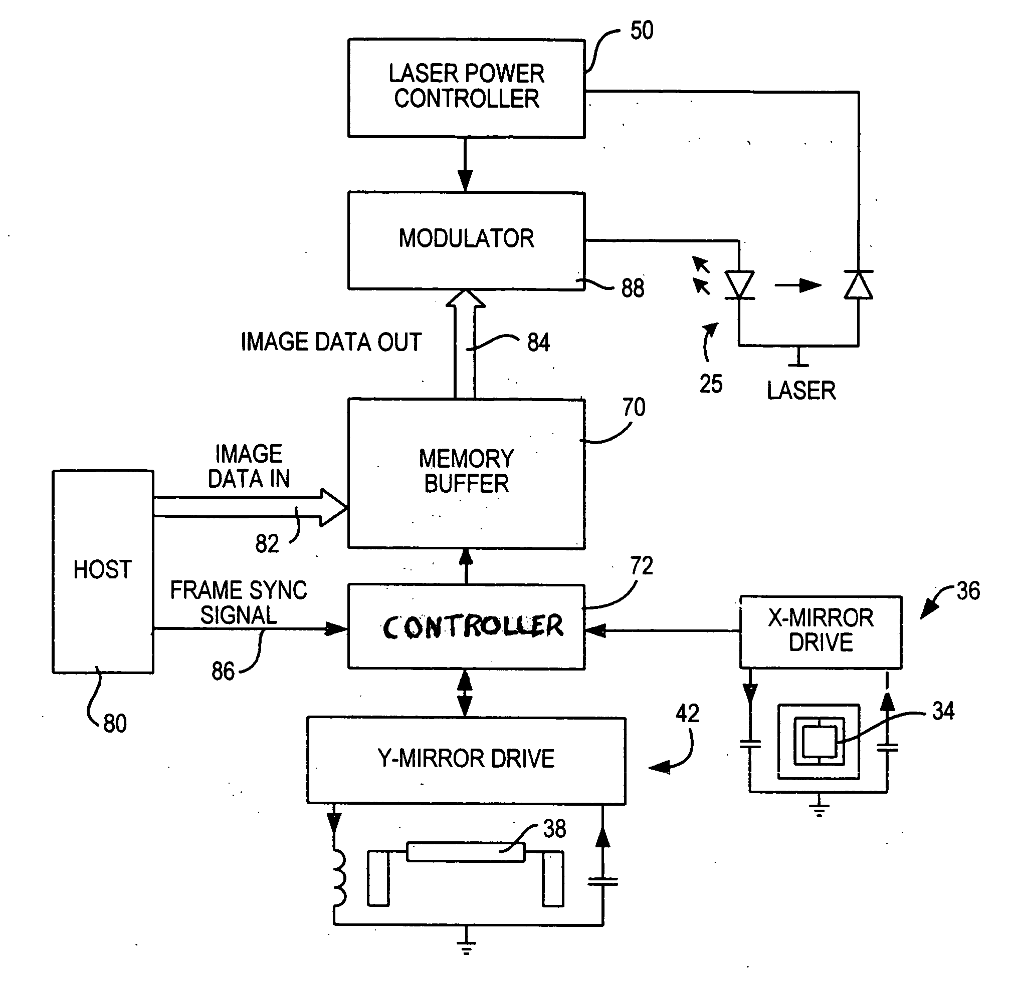
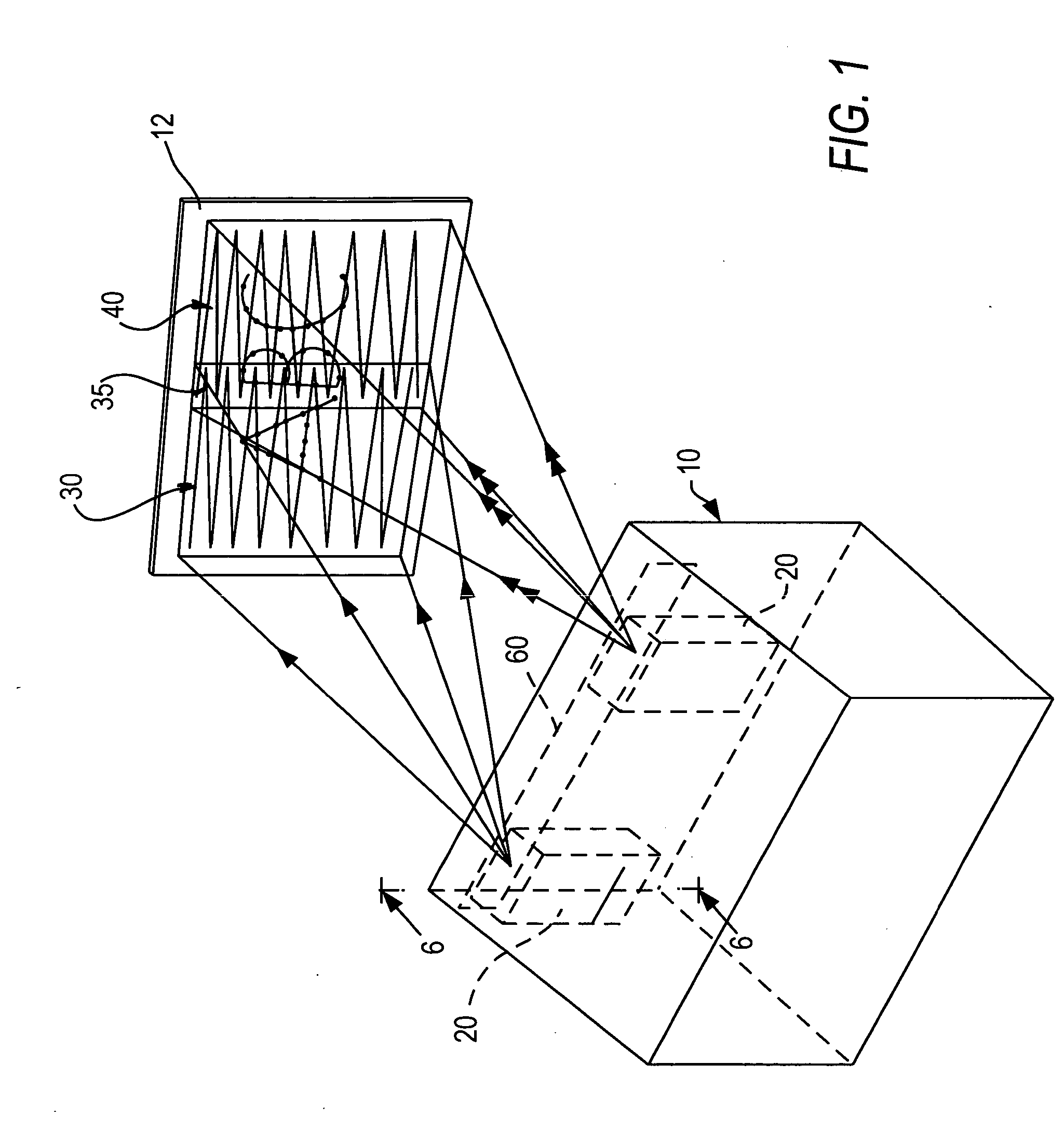
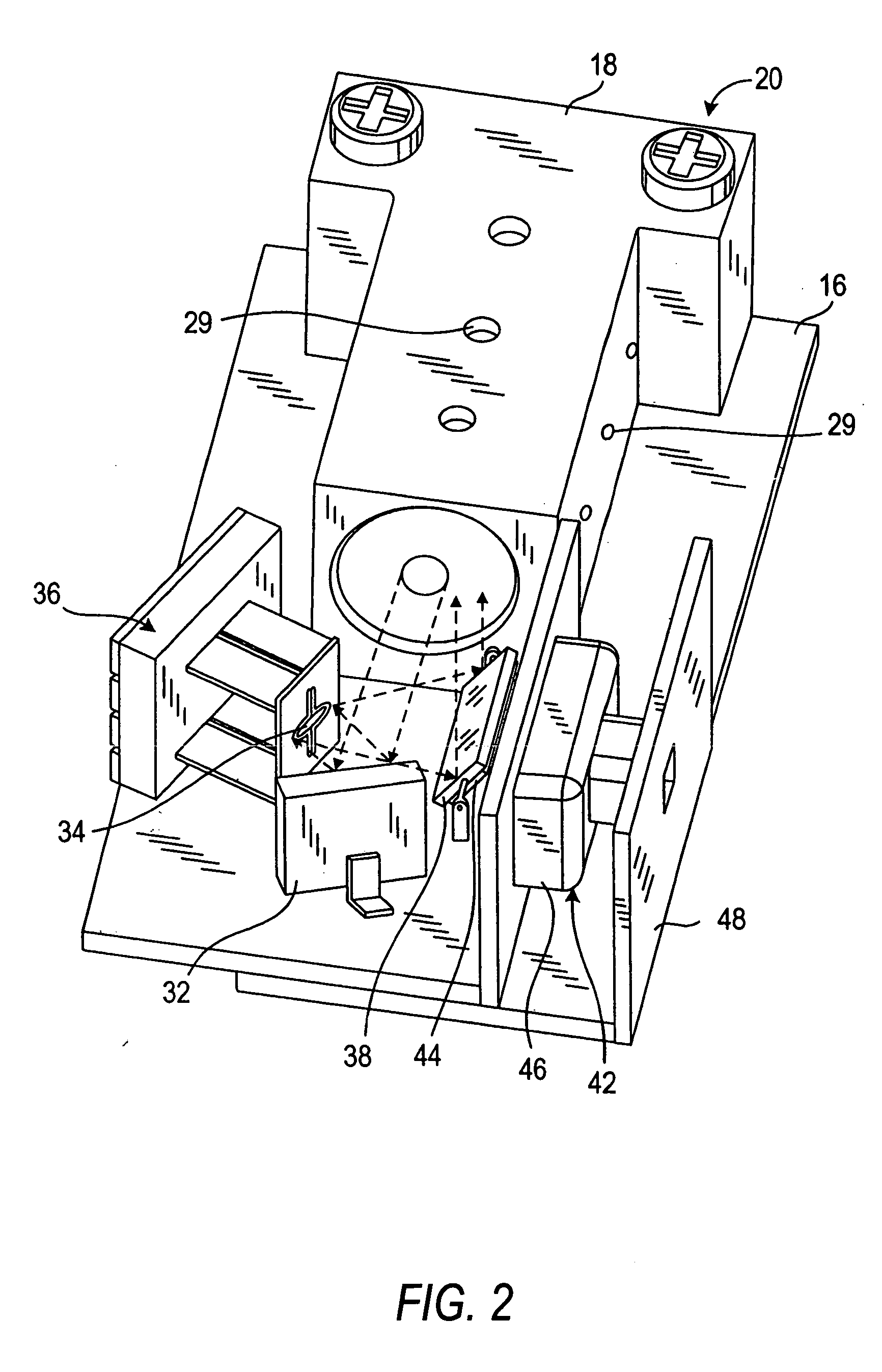
[0035] Reference numeral 10 in FIG. 1 generally identifies a housing in which a plurality of lightweight, compact, image projection modules 20, as shown in FIG. 2, is mounted. Each module 20 is operative for projecting a two-dimensional image at the same distance from the module. As described below, each image is comprised of illuminated and non-illuminated pixels on a raster pattern 30, 40 of scan lines swept by a scanner in module 20, and the two images are combined together to form a single image of large size. Both raster patterns 30, 40 preferably have the same optical horizontal scan angle extending along the horizontal direction, and the same optical vertical scan angle extending along the vertical direction, of the respective image.

[0036] The parallelepiped shape of the housing 10 represents just one form factor in which the modules 20 may be incorporated. In the preferred embodiment, each module 20 measures about 30 mm×15 mm×10 mm or about 4.5 cubic centimeters. This compa...


PUM


Abstract

A plurality of image projection modules is operative for causing selected pixels in overlapping raster patterns to be illuminated to produce a large size image of high resolution of VGA quality in monochrome or color. The selected pixels in an overlap region of the patterns are illuminated at a lesser intensity to provide uniform brightness over the image. Multiple single mode lasers, or a multimode laser with an aperture stop, are employed to increase laser output power. Speckle noise is reduced by controlling the optical transmission characteristic of a projection screen. Three-dimensional images are generated by moving the screen. Cross-coupling between drive and feedback mechanisms in image projection is reduced for better image quality.

Description

BACKGROUND OF THE INVENTION [0001] 1. Field of the Invention [0002] The present invention generally relates to projecting two-dimensional images of large size, especially using single mode laser sources or multimode laser sources, to reducing speckle noise, to creating three-dimensional displays, and to minimizing cross-coupled signals in drive mechanisms and pick-up mechanisms used in image projection. [0003] 2. Description of the Related Art [0004] It is generally known to project a two-dimensional image on a screen based on a pair of scan mirrors which oscillate in mutually orthogonal directions to scan a laser beam over a raster pattern. However, the known image projection systems project an image of limited resolution, typically less than a fourth of video-graphics-array (VGA) quality of 640×480 pixels, and of limited size. In the case of a color image formed by laser beams of different wavelengths (colors), some laser sources, for example, red semiconductor single mode lasers ...

Claims


Application Information

Patent Timeline
Patent Type & Authority Applications(United States)
IPC IPC(8): G03B21/00
CPCG03B21/14G03B35/18G03B37/04H04N9/3129G03B21/208
Inventor DVORKIS, PAULGOLDMAN, RONTAN, CHINHYAVID, DMITRIYWOOD, FREDERICK F.
Owner MICROVISION
Why Eureka
Try Eureka