A wireless power transmission mechanism and a high-voltage power-taking wireless power transmission system

A wireless power transmission and high-voltage technology, applied to circuits, inductors, transformers, etc., can solve the problems of system frequency splitting, increase system nonlinearity, and complex splitting, and achieve the effect of eliminating cross-coupling and improving transmission performance

Active Publication Date: 2022-04-01
重庆华创智能科技研究院有限公司
View PDF14 Cites 0 Cited by
  • Summary
  • Abstract
  • Description
  • Claims
  • Application Information

AI Technical Summary

Problems solved by technology

However, the appearance of multi-relay structure in WPT system increases the complexity of the system. Due to the cross-coupling between multi-coils, a series of new design problems are introduced in the system: 1) Due to the influence of cross-coupling, the resonance parameters of the system 2) Since the cross-coupling increases the nonlinearity of the system, frequency splitting occurs in the system, and the splitting situation is very complicated; 3) The power multipath transmission brought about by cross-coupling affects the system transmission power, Efficiency has a huge impact
However, since these methods only deal with the cross-coupling problem passively, and do not fundamentally eliminate the cross-coupling, the results are not very ideal.

Method used


Image

  • A wireless power transmission mechanism and a high-voltage power-taking wireless power transmission system
  • A wireless power transmission mechanism and a high-voltage power-taking wireless power transmission system
  • A wireless power transmission mechanism and a high-voltage power-taking wireless power transmission system

Examples


Embodiment 1

[0045] This embodiment provides a wireless power transmission mechanism, including a transmitting unit, a receiving unit, and a plurality of relay units sequentially arranged between the transmitting unit and the receiving unit, and the transmitting coil of the transmitting unit passes through the relay line of the relay unit The coil transmits the radio energy to the receiving coil of the receiving unit;

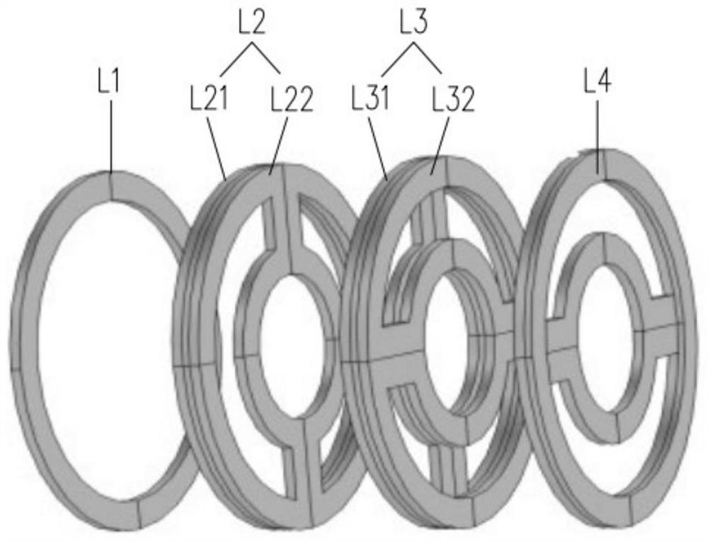
[0046]The relay coil of each relay unit adopts a double-layer coil structure, and each relay coil includes a front relay sub-coil and a rear relay sub-coil wound by a wire;

[0047] The front relay sub-coil of a relay unit is adjacent to the transmitting coil of the transmitting unit or the rear relay sub-coil of the previous relay unit, and the rear relay sub-coil of a relay unit is adjacent to the receiving coil of the receiving unit or the next relay unit The pre-relay sub-coils of different units are adjacent; the adjacent coils between different units are coupled, and ...

Embodiment 2

[0059] This embodiment provides a wireless power transmission mechanism. On the basis of Embodiment 1, it also includes an insulator, such as Figure 8 As shown, the transmitting coil, relay coil and receiving coil are set on the shed of the insulator in sequence; the transmitting coil is set on the insulator at one end close to the high-voltage line, and the receiving coil is set at the end close to the electrical equipment .

[0060] When the coil is wound, a through hole is formed between the upper D-shaped coil and the lower D-shaped coil of the upper and lower double D-shaped coils, and between the left D-shaped coil and the right D-shaped coil of the left and right double D-shaped coils. The through holes cover the upper and lower double D-shaped coils and the left and right double D-shaped coils on the insulator.

[0061] The wireless power transmission mechanism with insulators of this embodiment is applied to high-voltage power-taking places, and each coil is sleeved...

Embodiment 3

[0063] This embodiment provides a wireless power transmission system for high-voltage power acquisition, such as Figure 9 As shown, it includes a high-voltage power-taking device, a wireless power transmission mechanism and an electrical device, and the wireless power transmission mechanism adopts the wireless power transmission mechanism of Embodiment 1 or Embodiment 2;

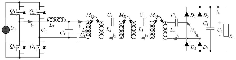
[0064] The high-voltage power-taking device inducts energy from the high-voltage line through the power-taking CT and converts it into constant-voltage DC power. The wireless power transmission mechanism inverts the DC power into AC power for wireless transmission, and transmits the received high The high-frequency alternating current is converted into direct current, and the electric equipment on the low-voltage side is powered by the direct current.

[0065] The wireless power transmission mechanism of this embodiment includes a power generating unit, a relay unit and a receiving unit. The power generati...


PUM


Abstract

The invention belongs to the technical field of magnetic coupling wireless power transmission, and in particular relates to a wireless power transmission mechanism and a high-voltage power-taking wireless power transmission system. The mechanism includes a transmitting unit, a plurality of relay units and a receiving unit arranged in sequence, and the transmitting coil of the transmitting unit transmits electric energy to the receiving coil of the receiving unit through the relay coil of the relay unit; each relay coil has a double-layer structure , including the front relay sub-coil and the rear relay sub-coil wound by a wire; the front relay sub-coil is close to the receiving coil, the rear relay sub-coil is far away from the receiving coil, the adjacent coils of different units are coupled, and the Non-adjacent coils are decoupled. Each relay coil in the multi-level relay unit of the present invention adopts a double-layer coil structure, and the adjacent coils between different units are coupled, and the non-adjacent coils between different units are decoupled, thereby eliminating the coupling between non-adjacent coils. Cross-coupling improves the transmission performance of the wireless power transmission system.

Description

technical field [0001] The invention belongs to the technical field of magnetic coupling wireless power transmission, and in particular relates to a wireless power transmission mechanism and a high-voltage power-taking wireless power transmission system. Background technique [0002] At present, the power supply methods of online monitoring equipment for high-voltage lines mostly use batteries, solar panels or wind power generation. Regular replacement of batteries will consume a lot of manpower and material resources, and there will be great safety hazards; wind and solar power generation will be limited by natural environmental conditions, and the application limitations will be relatively large. In recent years, a new type of power supply solution for online monitoring equipment of high-voltage transmission lines that combines Wireless Power Transfer (WPT) technology with Current Transformer (CT) has attracted widespread attention and is considered to be the solution An ...

Claims


Application Information

Patent Timeline
Patent Type & Authority Patents(China)
IPC IPC(8): H02J50/00H02J50/50H02J5/00H01F38/14H01F27/28H01F27/00
CPCH02J50/005H02J50/502H02J5/00H01F27/006H01F27/28H01F38/14
Inventor 王智慧左志平李小飞苏国栋
Owner 重庆华创智能科技研究院有限公司
Why Eureka
Try Eureka