STP root guard

Inactive Publication Date: 2006-05-04
CISCO TECH INC
View PDF17 Cites 41 Cited by
  • Summary
  • Abstract
  • Description
  • Claims
  • Application Information

AI Technical Summary

Problems solved by technology

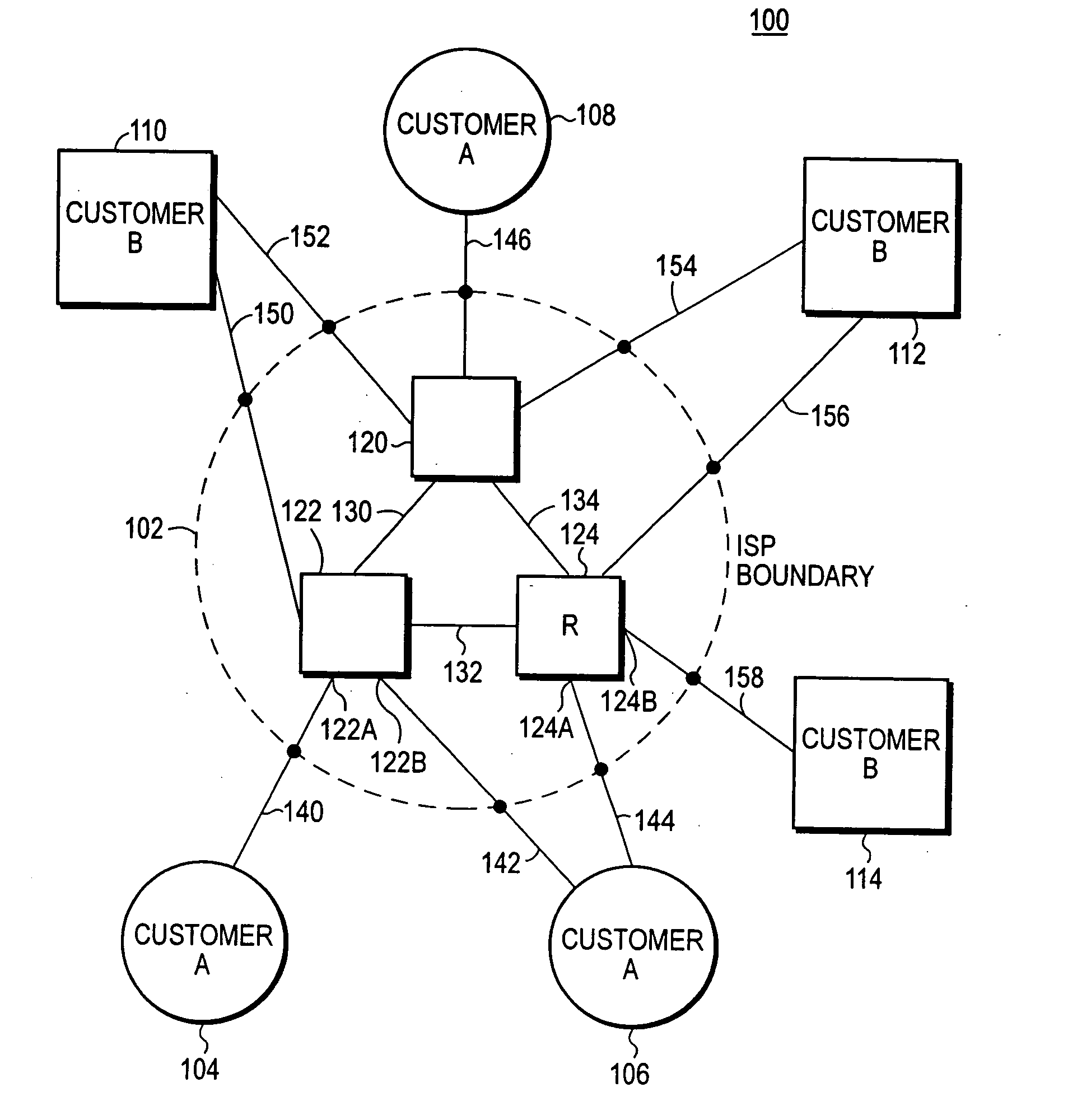
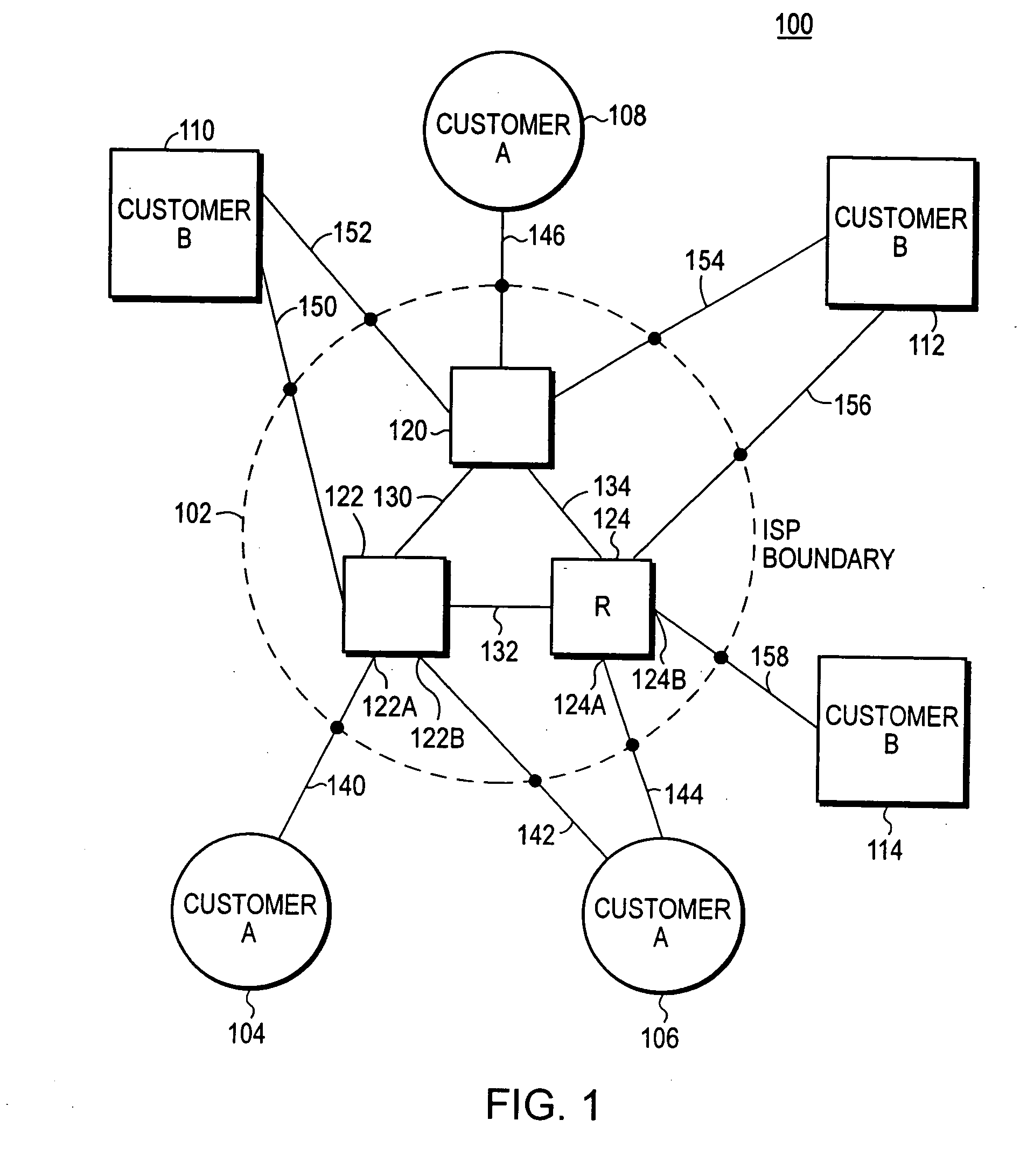
A problem arises when the layer 2 network of L2 switches extends over networks administered by different people.
In the event that the root switch is placed by STP in the customer's network, then that customer will carry traffic for all other customers of the ISP, and this is an undesirable situation.

Method used


Image

  • STP root guard
  • STP root guard
  • STP root guard

Examples


example

[0096] A possible implementation to show the flag follows:

PortVlanPort-StateRoot guardConsole> (enable) show spantree rootguard1 / 11root-inconsistentenabled1 / 21not-connecteddisabled2 / 11not-connecteddisabled2 / 21forwardingdisabled. . .. . .. . .. . .Console> (enable) show spantree rootguard 1 / 1-2, 4 / 21 / 11root-inconsistentenabled1 / 21not-connecteddisabled4 / 21forwardingenabledConsole> (enable) show spantree rootguard 33 / 43not-connecteddisabled5 / 13root-inconsistentdisabled5 / 23forwardingdisabled5 / 33forwardingenabled

Syslog Messages

New syslog messages are required to notify the user of the actions taken by the new root guard feature:

The following message will be printed when the feature is enabled or disabled on a port:

console>(enable) SPANTREE-5-ROOTGUARDENABLE: rootguard is now [enabled / disabled] for port [in No] / [pNo]

The following message will be printed when a port with the root guard enabled leaves the designated role:

console>(enable) SPANTREE-2-ROOTGUARDBLOCK: port [mNo] / [pN...


PUM


Abstract

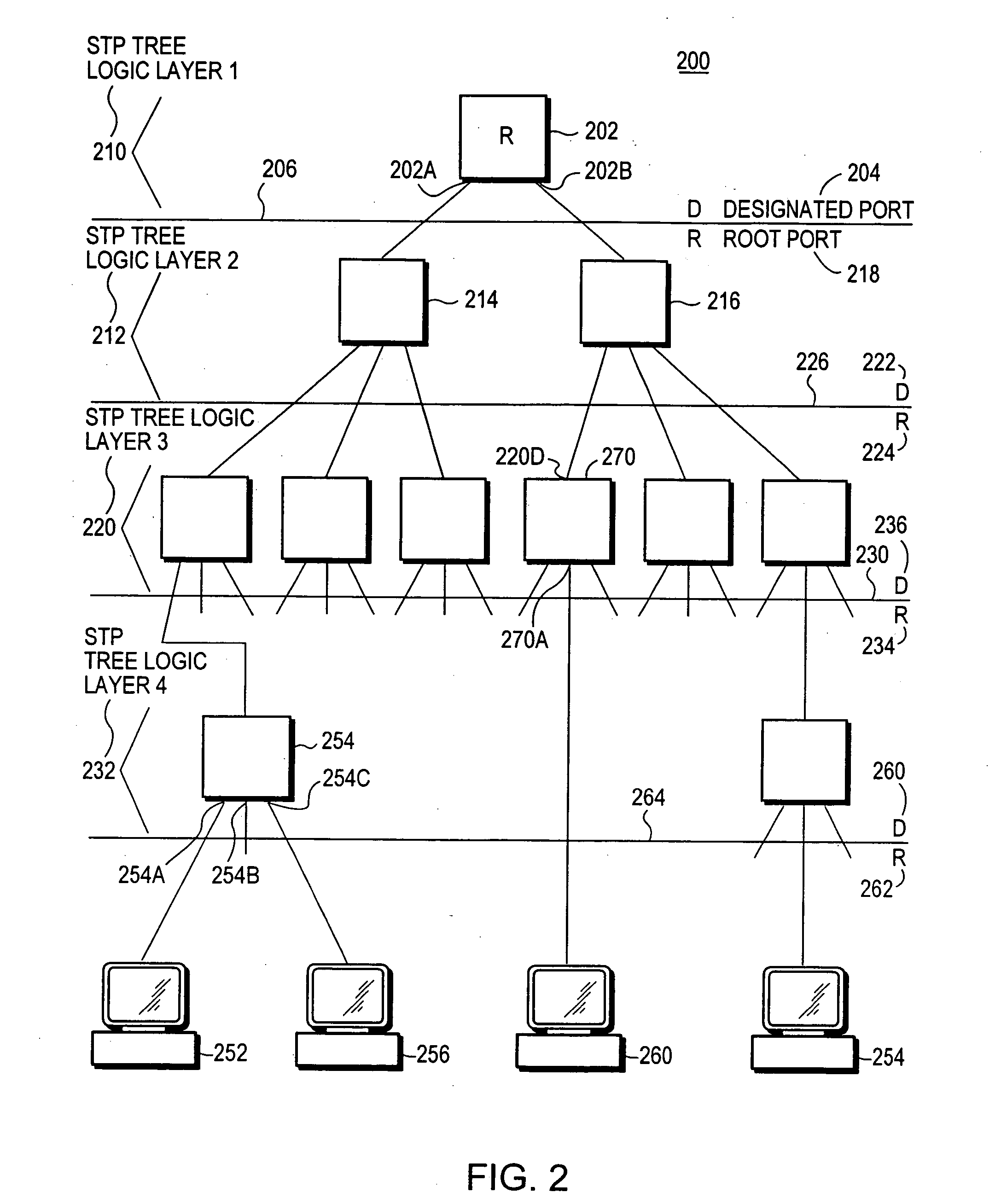
A method of managing a computer network switch is disclosed. The method has the steps of: setting a port of the switch to root guard protected status (RG status); selecting by a spanning tree protocol (STP) the port as a designated port; and setting said port into blocked status, in response to said port being both in root guard protected status and selected by STP as a root port. By setting a port to root guard protected, the port is prevented from becoming a designated port, and so then forcing the root port to remain in a desired core network.

Description

RELATED CASES [0001] This patent is a continuation of U.S. patent application Ser. No. 09 / 658,880 filed on Sep. 11, 2000 date, now issued as U.S. Pat. No. ______ on ______ date.FIELD OF THE INVENTION [0002] This invention relates to layer 2 computer networks utilizing a Spanning Tree Protocol (STP), and more particularly to the operation of multiple networks connected by layer 2 switches and using a common Spanning Tree Protocol. BACKGROUND OF THE INVENTION [0003] It is a common engineering practice for an entity which provides network applications for a number of customers to interconnect the networks using Layer 2 switches. That is, the network is connected as a Layer 2 (L2) network. For example, an Internet Service Provider (ISP) ordinarily has a core network. Each customer has his own customer network. When the networks are interconnected as a Layer 2 network, L2 switches interconnect the ISP core network with each customer's Layer 2 network. [0004] The Spanning Tree Protocol (S...

Claims


Application Information

Patent Timeline
Patent Type & Authority Applications(United States)
IPC IPC(8): H04L12/28
CPCH04L45/02H04L45/18H04L45/48
Inventor BENEDETTO, MARCO DIMELLACHERUVU, RAMANAMAHAJAN, UMESH
Owner CISCO TECH INC
Why Eureka
Try Eureka