

Cell phone with shiftable keypad
- Summary
- Abstract
- Description
- Claims
- Application Information
AI Technical Summary
Benefits of technology
Problems solved by technology
Method used
Image


Examples
Embodiment Construction
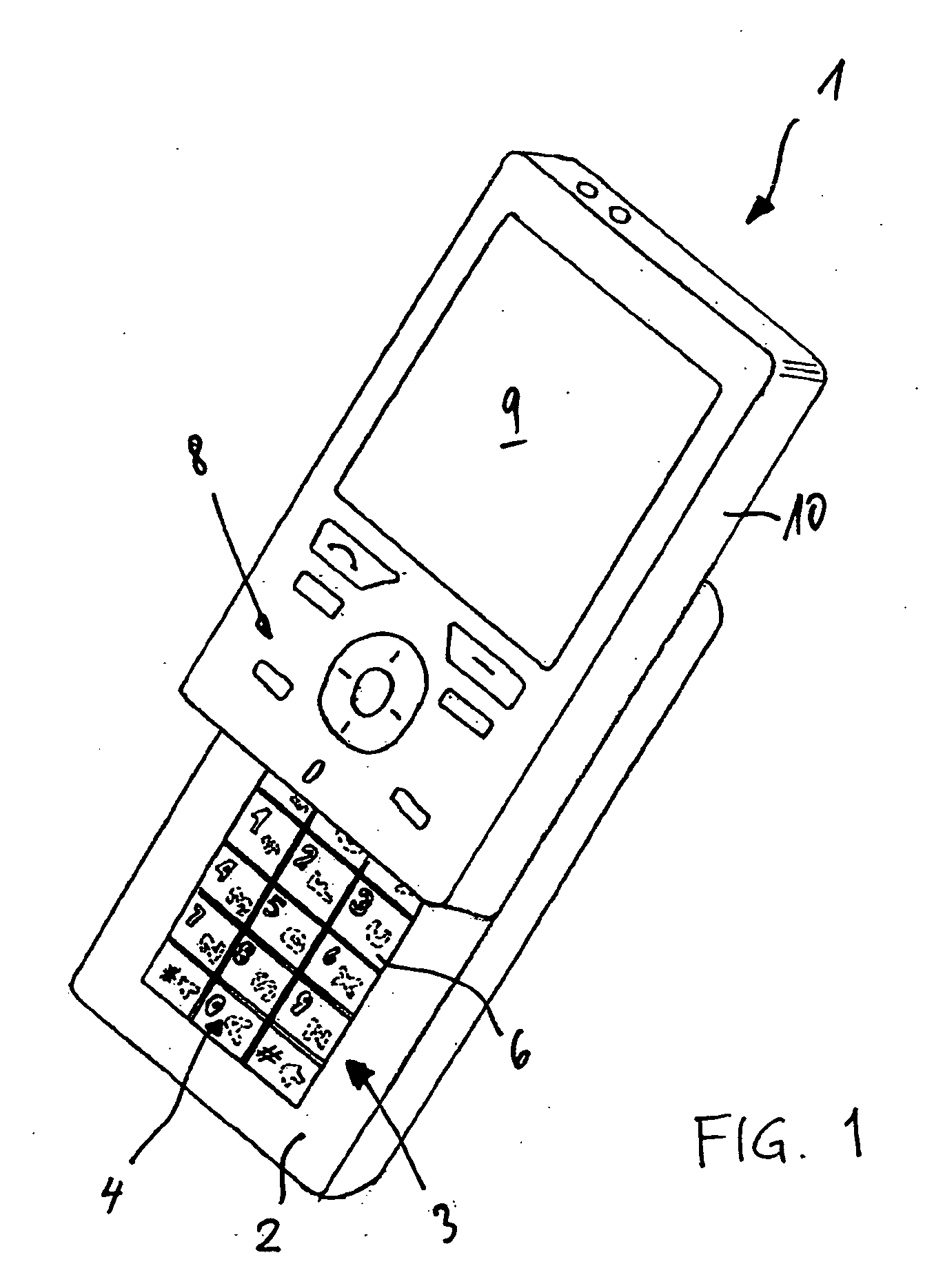
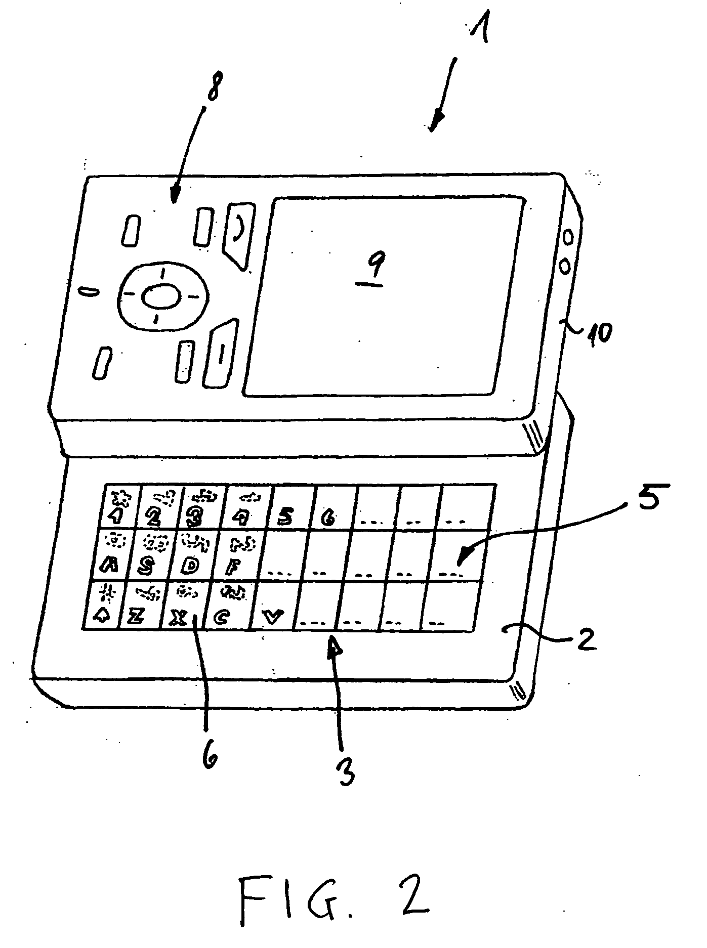
[0022] The FIGS. 1 and 2 show a preferred application of the inventive layer in an electronic device 1: in a cell phone. Both figures disclose the same cell phone with the same layer 2 extracted in two different directions. In this embodiment the layer 2 contains a keypad 3. The disclosed keypad 3 contains several mechanicals keys 6, but it is also conceivable that the keypad 3 contain just pressure sensors. The mechanical keys 6 or the conceivable pressure-sensor-keypad contain preferably piezo sensors. With the layer 2 extracted from the main casing 10 in the way showed in FIG. 1, the keypad 3 shows the display 4 in portrait format. The same keypad 3 can put on view another display 5, once the layer 2 is extracted in the other direction. In this way the keypad 3 shows the display 5 in the landscape format. In the landscape format, having more keys available, the cell phone can be used as a handheld or a pocket-PC. The keypad 3 in the landscape format can be equivalent to a miniatu...
PUM
 Abstract
Description
Claims
Application Information