Universal roller unit for a treadmill

Inactive Publication Date: 2006-07-20
WANG LEAO
View PDF5 Cites 24 Cited by
  • Summary
  • Abstract
  • Description
  • Claims
  • Application Information

AI Technical Summary

Benefits of technology

[0007] In consideration of the above-mentioned, the inventor of the present invention thinks that the displacement of the treadmill is not a regular action. In operational position, it's not required to use the roller sets. In storage position, it's not necessarily required to shift the treadmill. As a result, partial roller sets can be stored and kept away from the ground so as to eliminate the unexpected sliding shift. In brief, all rollers are pulled out only when it's really required to displace the treadmill. It's therefore an object of the invention to provide a room for accommodating a universal roller unit at the side wall of a rear bar of the supporting frame, thereby eliminating potential drawbacks of the conventional treadmill in respect of the design and the application.

Problems solved by technology

Although this prior art can exactly reach the expected effect, it's difficult for weak people to incline the heavy treadmill during its whole movement.
Even, this could lead to an unnecessary accident.
However, this kind of structure will cause an unexpected sliding or shaking when the treadmill is operated.
As a result, the safety of the user is seriously affected and it gradually becomes extinct on the market.
However, a swinging see-saw effect will be created when the treadmill is moved on an uneven surface, thereby leading to inconvenience and difficulty of the horizontal adjustment.

Method used


Image

  • Universal roller unit for a treadmill
  • Universal roller unit for a treadmill
  • Universal roller unit for a treadmill

Examples


Embodiment Construction

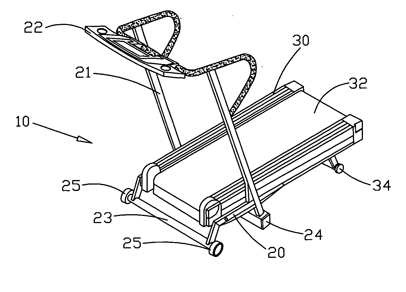
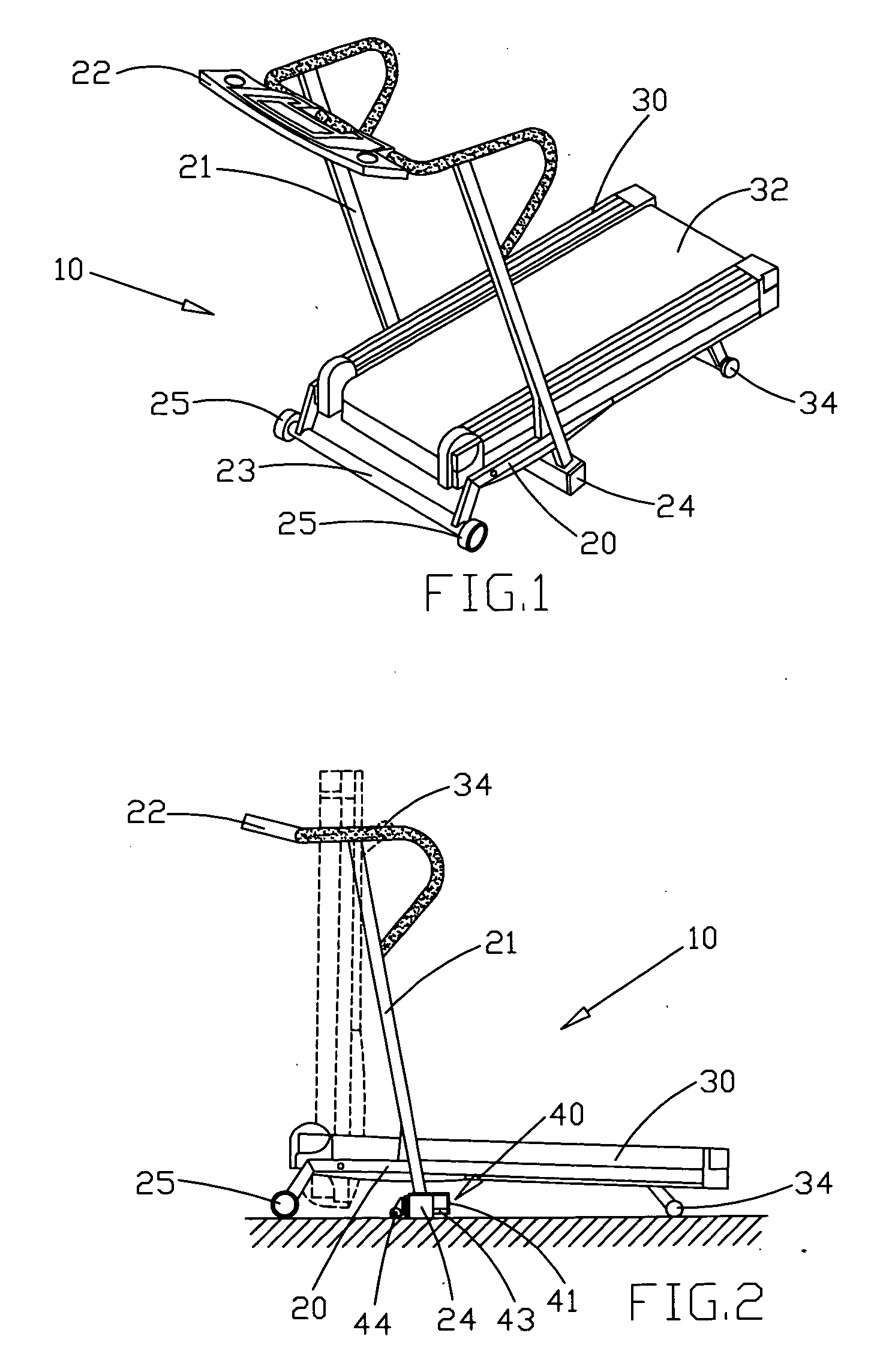
[0015] Referring to FIGS. 1, 2 and 3, a treadmill 10 in accordance with the invention includes:

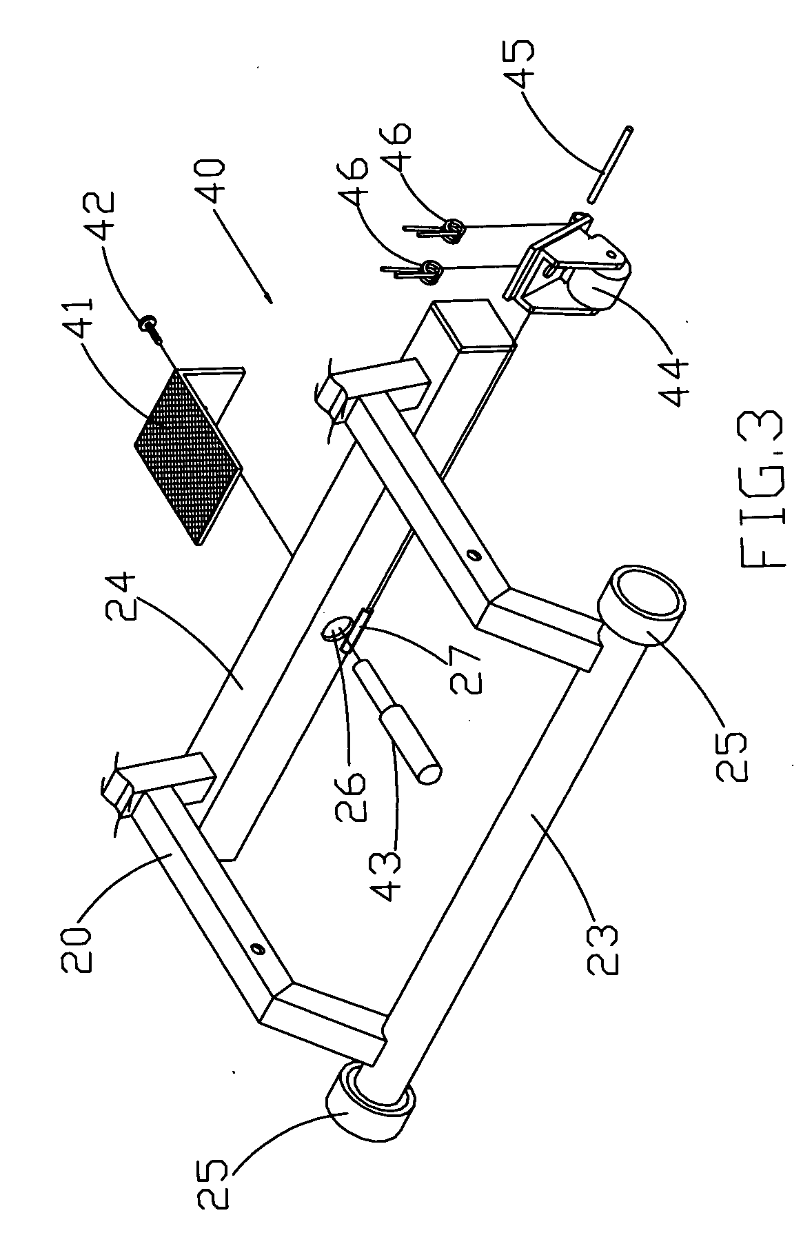
[0016] a supporting frame 20 positioned at the front end of a platform 30, a handrail 21 and an electric console 22 being disposed above the supporting frame 20, a front and a rear bar 23, 24 being attached to the supporting frame 20, a roller 25 being provided at both ends of the front bar 23, respectively, a universal roller unit 40 being provided in the middle of the rear bar 24;

[0017] a platform 30 in rectangular shape having a continuous belt 32 driven by a motor transmission unit (not shown) and movable around the platform 30, a support bar 34 being fitted to the bottom of the rear end of the platform 30. By assembling the above-mentioned components, the platform 30 on the supporting frame 20 can be folded in an upright storage position or in a flat operational position.

[0018] The universal roller unit 40 includes:

[0019] an angle iron 41 attached to the side wall of the rear bar ...


PUM


Abstract

A universal roller unit for a treadmill having a supporting frame and a platform. The supporting frame includes a front and a rear bar at the bottom thereof. A roller is pivotally connected to both ends of the front bar. A universal roller unit is attached to the middle part of the rear bar. When the treadmill is in a flat operational position, the universal roller unit may be attached to the side wall of the rear bar; when the treadmill is in a folded storage position, the universal roller unit may be pushed outwards to allow the universal roller to contact with the ground so that the universal roller and the rollers take the responsibility of supporting the whole weight of the treadmill and move the treadmill stably and freely in any direction.

Description

BACKGROUND OF THE INVENTION [0001] 1. Fields of the Invention [0002] The invention relates to a roller unit for a treadmill, and more particularly, to a roller unit having improved convenience in use. [0003] 2. Description of the Prior Art [0004] Rollers fitted at the bottom of treadmills are used to facilitate a smooth movement of the treadmill, thereby achieving the laborsaving effect. A typical product is disclosed in U.S. Pat. No. 5,672,140 that describes roller sets are axially and pivotably arranged at one end of the ground-touching cross bars at both sides of the bottom of the treadmill while the roller sets in storage position are not in contact with the ground. In use, the roller sets are used as a pivoting point to incline the main body of the treadmill so as to facilitate the movement of the treadmill. Although this prior art can exactly reach the expected effect, it's difficult for weak people to incline the heavy treadmill during its whole movement. Even, this could lea...

Claims


Application Information

Patent Timeline
IPC IPC(8): A63B22/02
CPCA63B22/02A63B2071/025A63B2210/50
Inventor WANG, LEAO
Owner WANG LEAO
Why Eureka
Try Eureka