Motorcycle rear stand

a rear stand and motorcycle technology, applied in the direction of work benches, lifting devices, crowbars, etc., can solve the problems of motorcycle leaning, prior art rear stand cannot commence to elevate the rear, and it is difficult for the pin on the rear stand to engage the axle bor

Inactive Publication Date: 2006-07-27
IDEANAMICS
View PDF5 Cites 23 Cited by
  • Summary
  • Abstract
  • Description
  • Claims
  • Application Information

AI Technical Summary

Benefits of technology

[0009] A motorcycle rear stand for lifting the rear end of a motorcycle having a pair of rear end lift pivot points and supported on a kickstand having first and second lift arms having inner and outer ends and a connector member connecting the first and second lift arms. Bike engagement members at the outer ends of each of the first and second lift arms are adapted to pivotally engage one side of a pair of motorcycle rear end lift pivot points. A side support member having a base member at one end and a pivot connection at the opposite end is connected pivotally to the outer end of the first lift arm to thereby enable the first and second lift arms to pivot relative to the side support members when the handle is moved.

Problems solved by technology

A problem associated with motorcycle rear stands is that motorcycles normally are retained in an upright position by a kickstand, which causes the motorcycle to lean over in the direction of the kickstand.
Because a motorcycle leans at an angle such that the vertical axis of the motorcycle is not perpendicular to the ground when the cycle is supported on a kickstand, the prior art motorcycle rear stand cannot properly align the bike engagement members with the rear axle projections on opposite sides of the motorcycle prior to lifting the bike inasmuch as the angled position of the motorcycle causes the rear wheel axle projection on the kickstand side of the motorcycle to be lower in elevation above the ground than the motorcycle rear axle projection on the opposite side of the motorcycle.
Consequently, the prior art rear stand cannot commence to elevate the rear of a motorcycle on a kickstand because it can securely engage only the lower, kickstand side axle projection and has little or no control over the opposite rear wheel axle projection.
Lifting the motorcycle in this condition could cause it to tip over.
When these motorcycles are supported on a kickstand, the axis of the rear wheel is non-parallel to the ground, making it difficult for a pin on a rear stand to engage the axle bore.

Method used


Image

  • Motorcycle rear stand
  • Motorcycle rear stand
  • Motorcycle rear stand

Examples


Embodiment Construction

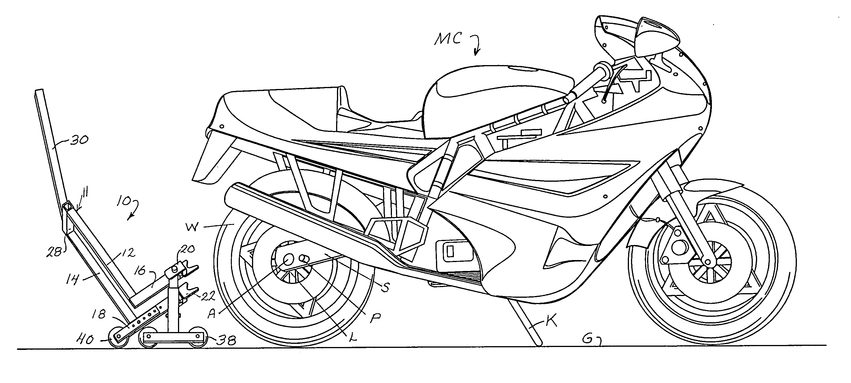
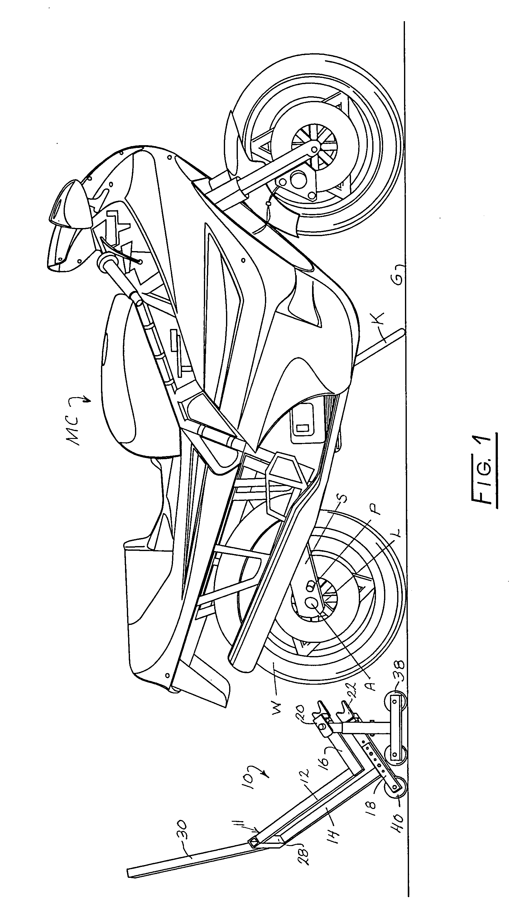
[0024]FIG. 1 shows a motorcycle MC supported on a kickstand K which projects from the lower, central portion of the left side of the motorcycle to a lifting surface or ground G. The rear end of the motorcycle has a rear wheel W mounted on an axle A which is supported in and projects from opposite sides of frame mounted swing arms S on opposite sides of the rear wheel W. The swing arms S have laterally projecting lift pivot points which may be pins P or lower lift arm surfaces L adapted to be engaged by bike engagement members mounted on a motorcycle rear stand 10 of the instant invention and described in detail herein below. Opposite ends of axle A also function as lift pivot points.

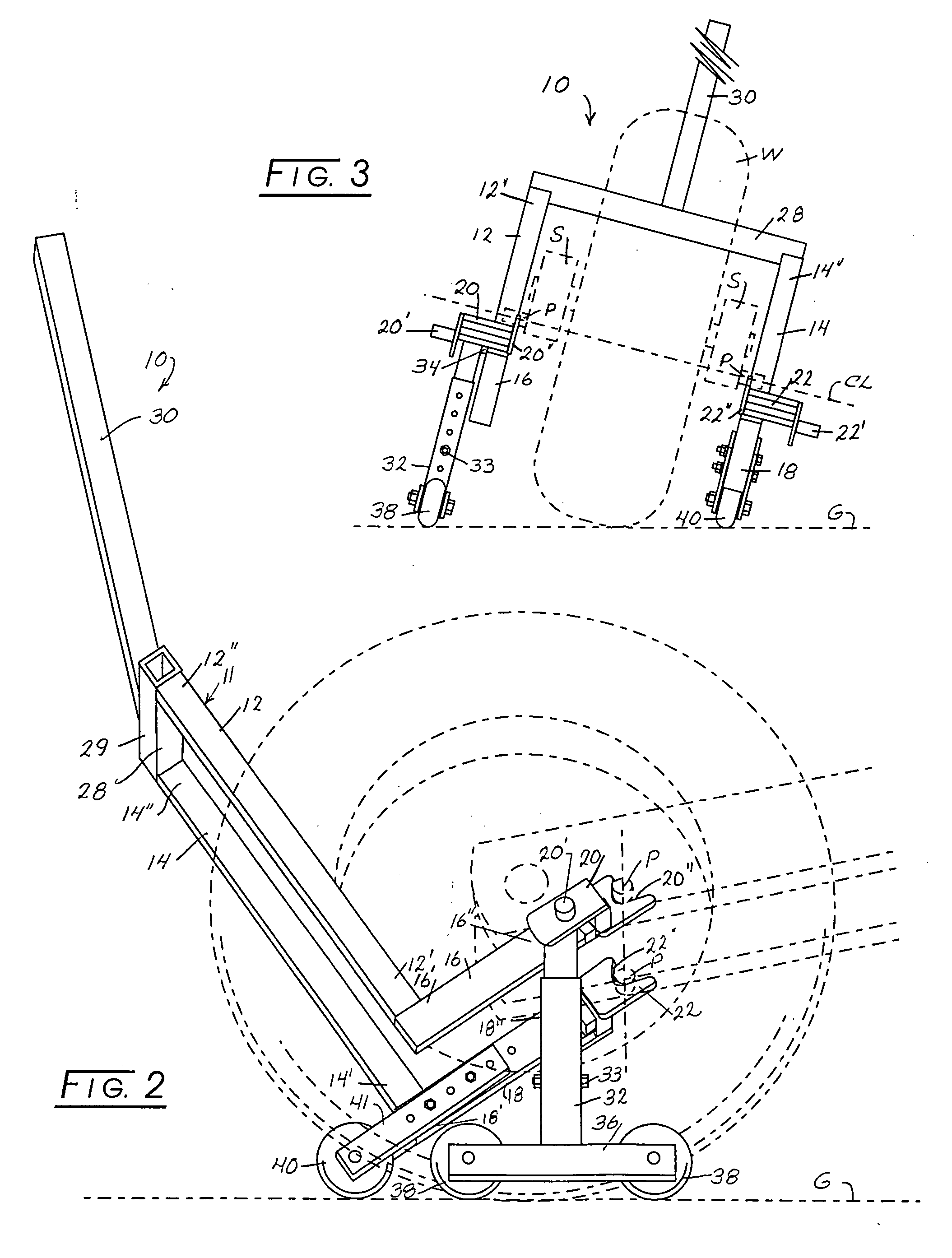
[0025] Referring to FIGS. 1 through 5 of the drawings, it may be seen that motorcycle rear stand 10 has a frame 11 comprising a pair of spaced legs 12 and 14, each having distal ends 12′ and 14′ and proximal ends 12″ and 14″. Lift arms 16 and 18 having inner ends 16′ and 18′ and outer ends 16″ and 18″ r...


PUM


Abstract

A motorcycle rear stand for lifting the rear end of a motorcycle having a rear end lift pivot member and supported on a kickstand having a frame with a pair of side support members, a stop surface at one end of the frame, a pivot mounted at different distances forwardly of the stop surface on each of the side members, a lift arm having a bike engagement member at its outer end mounted on the frame and projecting upwardly therefrom wherein pivotal movement of the frame simultaneously lifts the rear end of a motorcycle and levels the motorcycle from an initial leaning position.

Description

CROSS-REFERENCES [0001] None. FIELD OF THE INVENTION [0002] This invention relates to a motorcycle rear stand. BACKGROUND OF THE INVENTION [0003] A motorcycle rear stand functions to move the rear end of a motorcycle between a first position in which both wheels of the motorcycle are on the ground and a second position in which the rear end of the motorcycle including the rear wheel are elevated above the ground. A problem associated with motorcycle rear stands is that motorcycles normally are retained in an upright position by a kickstand, which causes the motorcycle to lean over in the direction of the kickstand. One prior art motorcycle rear stand has a pair of spaced L-shaped side bars with wheels mounted at the vertex of the side bars and V- or U-shaped bike engagement members at the outer ends of the side bars, adapted to engage opposite sides of a motorcycle rear axle. The L-shaped side bars are connected by a U-shaped member which joins the upper ends of the side bars and at...

Claims


Application Information

Patent Timeline
Patent Type & Authority Applications(United States)
IPC IPC(8): B66F3/00
CPCB25H1/0014B66F15/00
Inventor KOBACKER, ALFRED J. IIZIMMERMAN, GARY P.
Owner IDEANAMICS
Why Eureka
Try Eureka