Back light module

Active Publication Date: 2006-08-24
CPT TECH GRP
View PDF3 Cites 7 Cited by
  • Summary
  • Abstract
  • Description
  • Claims
  • Application Information

AI Technical Summary

Benefits of technology

[0009] Accordingly, the present invention is directed to a back light module comprising a baffle plate capable of absorbing the impact force during the impact test so that the possibility of displacement of the light guide plate can be reduced and damage to the linear light source due to the displacement of the light guide plate can be effectively reduced. Thus, the reliability of the notebook computer can be effectively promoted.
[0019] In summary, because the baffle plate of the back light module, according to the present invention, is disposed between the linear light source and the light guide plate, the baffle plate can absorb the impact force during the impact test and thereby reduce the possibility of displacement of the light guide plate and thus reduce the possibility of damage to the linear light source due to the displacement of the light guide plate. Moreover, the Z-shaped baffle plate comprises the first deflection portion propped against the reflective mask, so the holding force of the reflective mask for resisting the displacement of the light guide plate toward the light guide plate can be efficiently increased so that the reliability of the notebook computer can be effectively promoted.

Problems solved by technology

As for impact test, as the reflective mask for light is difficult to firmly fix the light, and therefore the light guide plate may easily get displaced and because it is positioned proximate to the linear light source, and therefore the displacement of the light guide plate towards the linear light source may damage the linear light source.
However, as the ear portion may interfere with V-shaped notches, therefore the aforementioned technique of securing the light guide plate to the frame is not suitable for the light guide plate with V-shaped notches.
However, securing strength using the reflective mask 120 to hold the light guide plate 130 and using the double sided tape 140 to attach the reflective mask 120 to the frame 110 is not adequate, and during the impact test, the light guide plate 130 come loose from the reflective mask 120 and damage the linear light source.

Method used


Image

  • Back light module
  • Back light module
  • Back light module

Examples


Embodiment Construction

[0031] Various specific embodiments of the present invention are disclosed below, illustrating examples of various possible implementations of the concepts of the present invention. The following description is made for the purpose of illustrating the general principles of the invention and should not be taken in a limiting sense. The scope of the invention is best determined by reference to the appended claims.

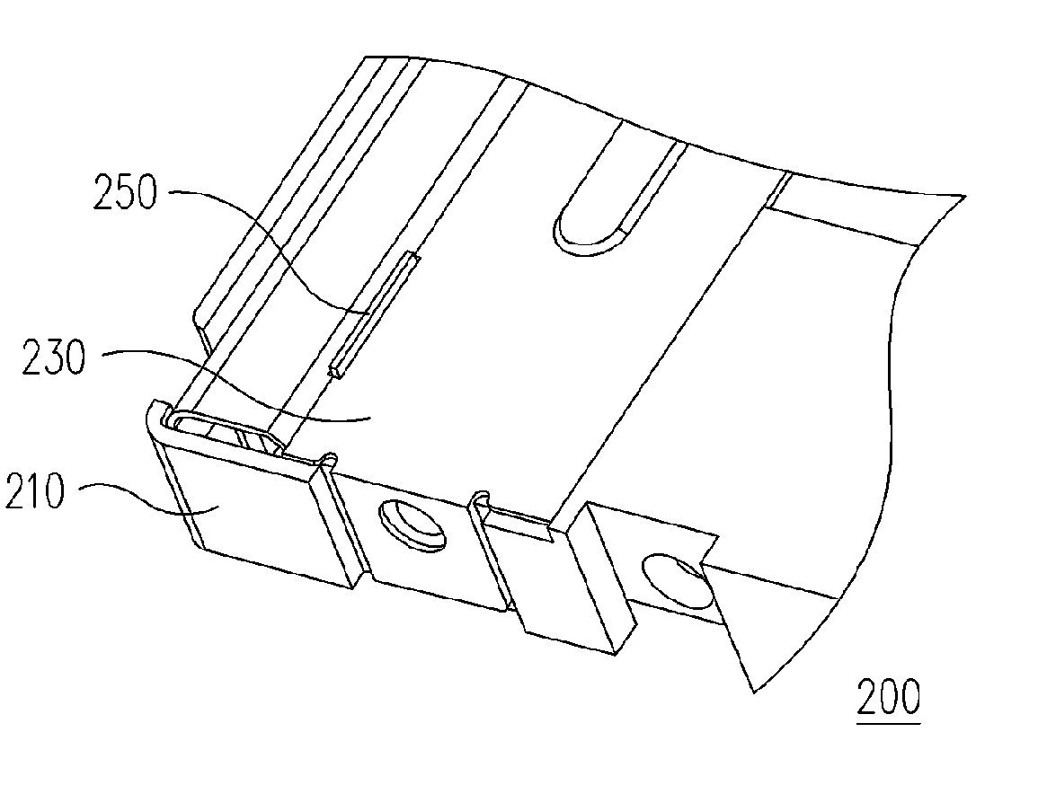
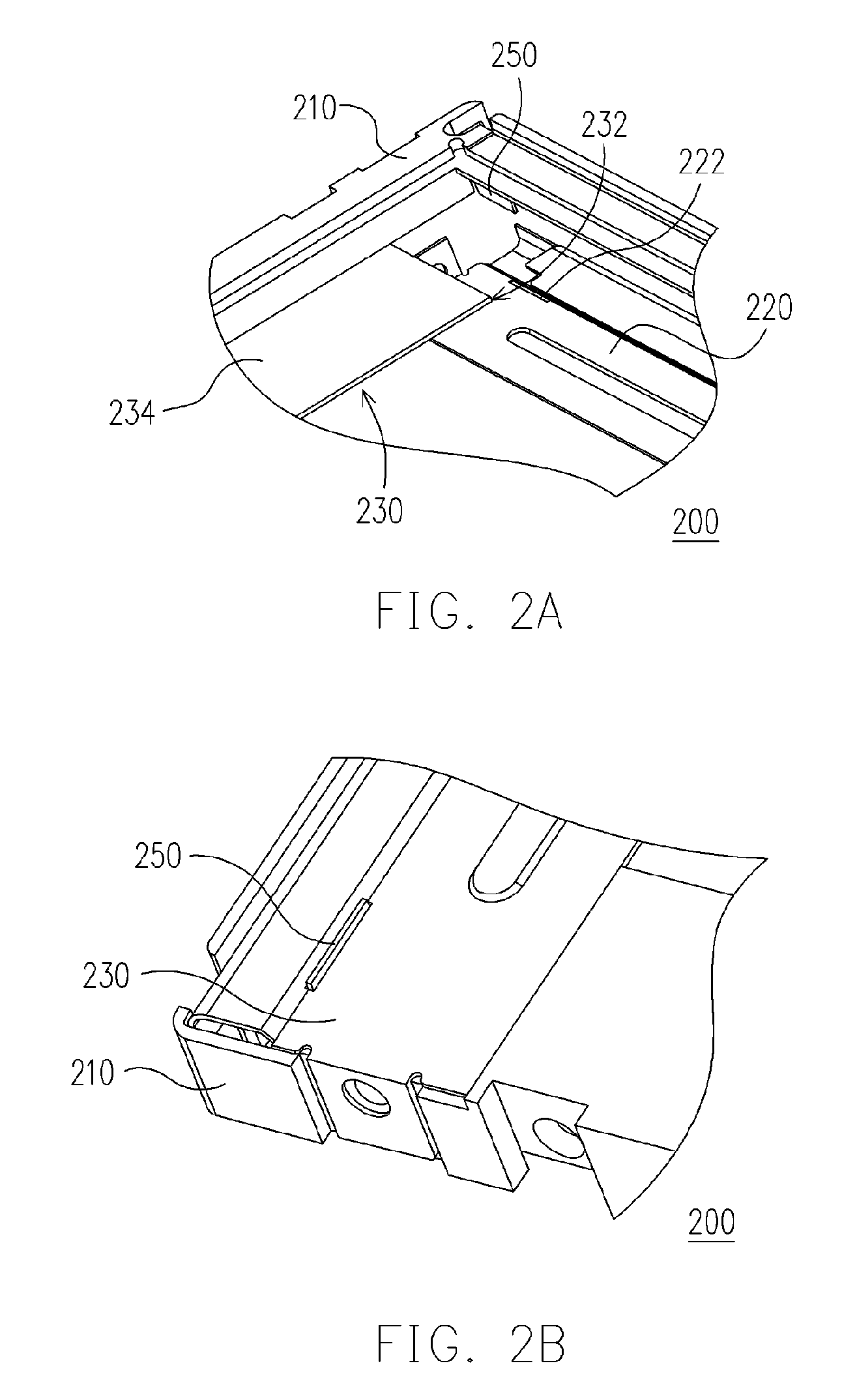
[0032]FIG. 2A is an exploded view of a baffle plate connected to a frame of a portion of a back light module according to one embodiment of the present invention. FIG. 2B is a perspective schematic view of a frame with a baffle plate assembled to a reflective mask having an opening of a back light module according to one embodiment of the present invention. FIG. 2C is a cross-sectional schematic view of a frame with a baffle plate assembled to a reflective mask having an opening of a back light module according to one embodiment of the present invention. Referring to FIGS. 2...


PUM


Abstract

A back light module is disclosed. The back light module comprises a frame, a reflective mask, a light guide plate, a linear light source and a baffle plate, wherein the reflective mask is installed in the frame. The linear light source is surrounded by the light guide plate and the reflective mask. The baffle plate is disposed between the linear light source and the light guide plate and the baffle plate is connected to the reflective mask and the frame. The baffle plate disposed between the linear light source and the light guide plate is adapted for absorbing impact force during the impact test and reducing the possibility of displacement of the light guide plate. Thus, the possibility of damage to the linear light source due to displacement of the light guide plate can be effectively reduced. Thus, the reliability of the notebook computer can be effectively promoted.

Description

BACKGROUND OF THE INVENTION [0001] 1. Field of the Invention [0002] The present invention relates to a back light module. More particularly, the present invention relates to a back light module capable of reducing damage to the linear light source thereof by the impact of the light guide plate during the impact test. [0003] 2. Description of Related Art [0004] With the advancement of information technology, the personal computer is developing toward portable notebook computer as the portable notebook computer provides convenience of portability and access to information. Therefore the notebook computer is highly attractive to a variety of people for business, correspondence, research, entertainment and the like. Different types of the portable notebook computers have been extensively developed in order to meet various needs of users. [0005] Generally, in order to ensure the quality of the notebook computer such as operation and stability under various conditions, prior to shipping o...

Claims


Application Information

Patent Timeline
IPC IPC(8): F21V7/04
CPCG02B6/0091G02B6/0093
Inventor HSIAO, CHIH-CHUNLIAO, CHENG-MIN
Owner CPT TECH GRP
Why Eureka
Try Eureka