
Magnetic encoder and bearing

Active Publication Date: 2007-07-05
NSK LTD
View PDF6 Cites 36 Cited by
  • Summary
  • Abstract
  • Description
  • Claims
  • Application Information

AI Technical Summary

Benefits of technology

[0013] According to the magnetic encoder of the invention, the magnet portion is constructed by a constitution of including the magnetic member and the resin and therefore, a comparatively large amount of a magnetic powder can be mixed to a rubber magnet, the magnetic encoder having an excellent magnetic property can be provided, further, an anisotropic magnet facilitated to be molded by injection molding in a state of being applied with a magnetic field (magnetic field molding) and indispensable for manifesting an excellent magnetic property can be provided.
[0014] Further, according to the magnetic encoder of the invention, the resin is preferably a thermoplastic resin, further preferably includes a thermoplastic resin including a soft segment in a molecule and therefore, a crack can be prevented from being brought about at the magnet portion, and reliability can be promoted.
[0015] Further, according to the magnetic encoder of the invention, the magnetic encoder further includes a fixed member comprising a magnetic material, the magnet portion and the fixed member are bonded by an adhering agent including at least one of a phenolic resin based and an epoxy resin based and therefore, exfoliation is difficult to be brought about at an adhering portion and reliability can be promoted.
[0016] Further, according to the magnetic encoder of the invention, the magnet portion is molded by injection molding of a disk gate type and therefore, a magnet material is molded by injection molding in a shape of a radial circle, and is provided with a high mechanical strength without producing a weld portion, and is excellent in a magnetic property in which an orientation degree of the magnetic member included in the encoder is high.

Problems solved by technology

Therefore, even under the above-described temperature environment, a property thereof of fixedly adhering to the slinger is maintained and a problem of exfoliation is difficult to be brought about.

Method used


Image

  • Magnetic encoder and bearing
  • Magnetic encoder and bearing
  • Magnetic encoder and bearing

Examples


first embodiment

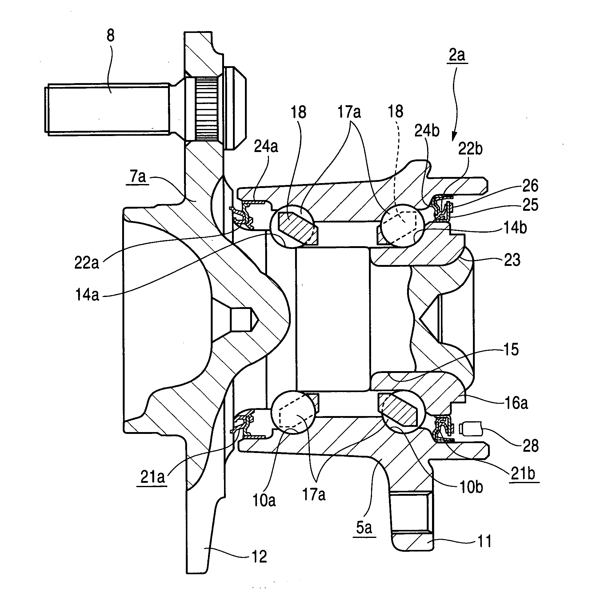
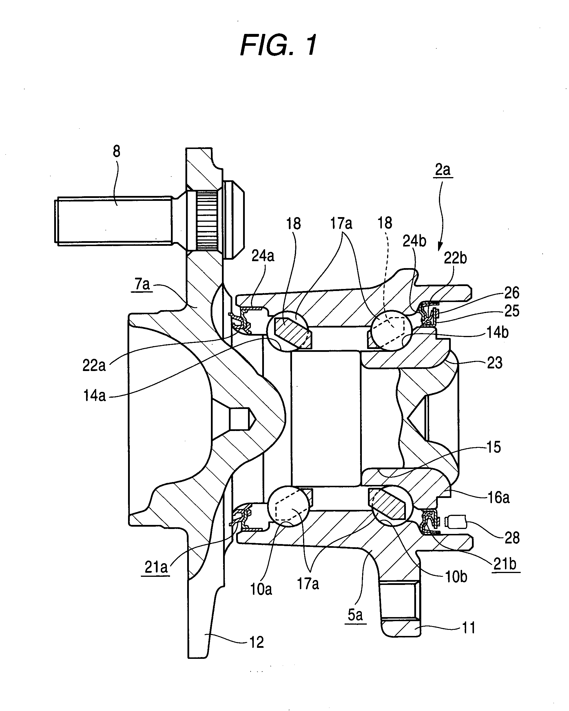
[0093]FIG. 1 shows a case of applying the invention to the hub unit 2a constituting a bearing for a wheel for supporting a driven wheel supported by a suspension of an independent suspension type of an example of an embodiment of the invention. Further, a constitution and operation other than a characteristic of the invention are equivalent to those of a structure which has widely been known in a background art and therefore, an explanation thereof will be simplified and an explanation will be given centering on a characteristic portion of the invention as follows.

[0094] The hub unit bearing 2a includes the outer ring 5a constituting a fixed ring, the hub 7a and the inner ring 16a constituting rotating rings (rotating members) rotated integrally with the attaching flange 12 for fixing a wheel (not illustrated), the balls 17a, 17a constituting a plurality of rolling members rollably arranged in a peripheral direction between the outer ring 5a and the hub 7a and the inner ring 16, an...

second embodiment

[0181] Next, a detailed explanation will be given of a hub unit bearing constituting a bearing for a wheel for supporting a nondriven wheel supported by a suspension of an independent suspension type according to a second embodiment of the invention. Further, portions equivalent to those of the first embodiment are attached with the same notations and an explanation thereof will be omitted or simplified.

[0182] Although according to the first embodiment, the magnetic encoder 26 and the sensor 28 are of a type of being opposed to each other in an axial direction, according to hub unit bearing 30 of the embodiment, as shown by FIG. 9, a magnetic encoder 31 and a sensor 32 are opposed to each other in a radial direction.

[0183] According the magnetic encoder 31 of the embodiment, a slinger 33 in a circular ring shape constituting a fixed member is outwardly fitted to be fixed to an outer peripheral portion of an inner end portion of the inner ring 16a, and a magnetic pole forming ring ...

third embodiment

[0186] Next, a detailed explanation will be given of a rolling bearing unit attached with a sealing apparatus attached with a magnetic encoder according to a third embodiment of the invention.

[0187] As shown by FIG. 10 and FIG. 11, a rolling bearing unit 40 including a magnetic encoder according to the embodiment includes the outer ring 41 constituting a fixed ring, an inner ring 42 constituting a rotating ring (rotating member), the balls 43 constituting a plurality of rolling members rollably arranged between a ring-like gap partitioned by the outer ring 41 and the inner ring 42 and held at equal intervals in a circumferential direction by a retainer 44, a hermetically sealing apparatus 45 arranged at an opening end portion of the ring-like gap, a magnetic encoder 46, and a sensor 47.

[0188] The hermetically sealing apparatus 45 includes the sealing member 50 mounted to an inner peripheral face of the outer ring 41, and a slinger 60 arranged on an outer side of the bearing rather...


PUM


Abstract

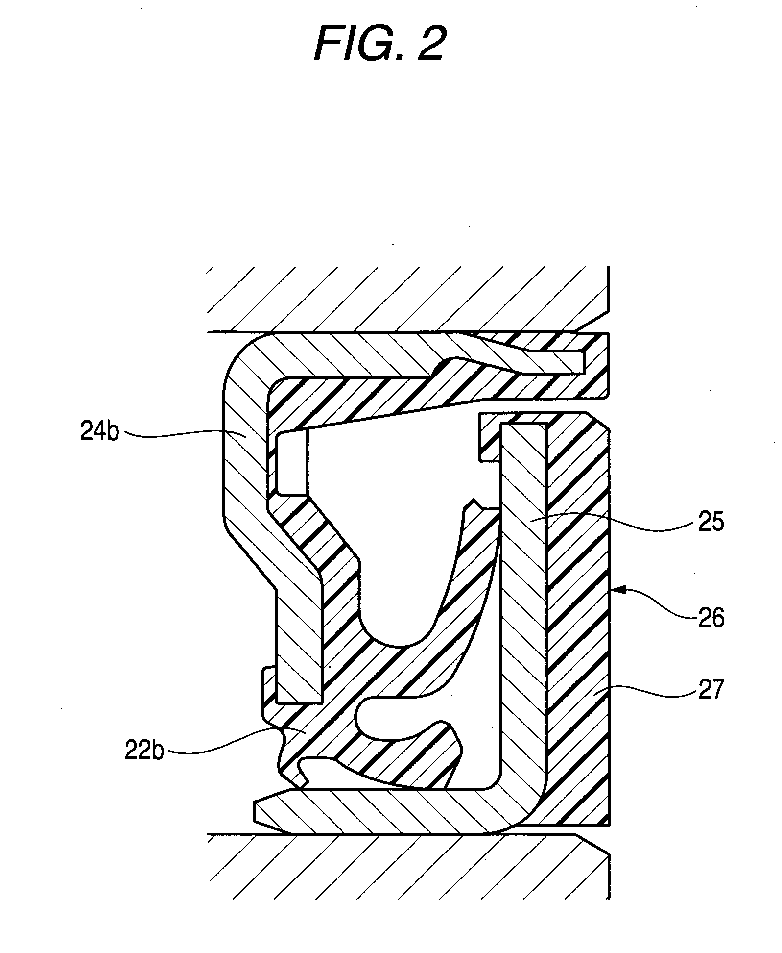
A magnet portion 27 of a magnetic encoder 26 includes a magnetic member and a resin, and a highly reliable magnetic encoder 26 having a high magnetic property and enabling to detect a rotational number with high accuracy, and a hub unit bearing 2a are provided. Further, the resin is preferably a thermoplastic resin and further preferably includes a thermoplastic resin including a soft segment in a molecule. Further, the magnetic encoder 26 further includes a fixed member 25 attached with the magnet portion 27 and comprising a magnetic material, and the magnet portion 27 and the fixed member 25 are bonded by an adhering agent including at least one of a phenolic resin based and an epoxy resin based.

Description

TECHNICAL FIELD [0001] The present invention relates to a magnetic encoder used for detecting a rotational number of a rotating member, and a bearing therefor. RELATED ART [0002] In a background art, there is known a rotational number detecting apparatus used for anti-skid used for preventing skidding (a phenomenon in which a wheel is slipped substantially in a stopped state) of an automobile, or a traction control (a control of unnecessary idle rotation of a drive wheel which is liable to be brought about in starting or in accelerating) for effectively transmitting a drive force to a road face or the like, including an encoder in a shape of a circular ring magnetized with N poles and S poles alternately in a circumferential direction, and a sensor for detecting a change in a magnetic field at a vicinity of the encoder for rotating the encoder along with rotation of a wheel by arranging the encoder along with a hermetically sealing apparatus for hermetically sealing a bearing for su...

Claims


Application Information

Patent Timeline
IPC IPC(8): G01P3/48F16C19/18F16C19/52F16C33/78G01P3/44G01P3/487
CPCG01P3/487F16C19/186G01P3/443F16C33/7879F16C2326/02F16C41/007F16J15/326G01D2205/80
Inventor YABE, TOSHIKAZUMURAKAMI, TAKESHIAIHARA, NARIAKITAKAJO, TOSHIMI
Owner NSK LTD
Learn More