

Magnetic material loaded with magnetic alloy particles and method for producing said magnetic material
- Summary
- Abstract
- Description
- Claims
- Application Information
AI Technical Summary
Benefits of technology
Problems solved by technology
Method used
Image

Examples
first embodiment (
Formation of FePt Alloy Particle)
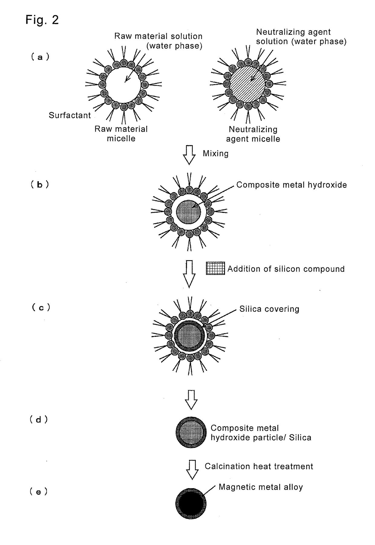
[0054](a) Production of Raw Material Micellar Solution
[0055]Iron nitrate (Fe(NO3)3.9H2O) and chloroplatinic acid (H2[PtCl6].xH2O) were added to 6 mL of pure water, so as to be 0.12 M in the total of Fe and Pt. Further, 18.82 mg of barium nitrate (Ba(NO3)2) (Ba: 0.012 M) was added. A charged amount of barium being an alkali-earth metal is 0.1 in molar ratio relative to the metals (Fe+Pt). 18.3 mL of octane and 3.6 mL of butanol were added to the aqueous solution as organic solvents to be an oil phase, and 3.52 g of CTAB was added as a surfactant. The solution was stirred for 30 minutes until it became uniform, and a raw material micellar solution was produced. Above operations are performed at room temperature. Meanwhile, plural raw material micellar solutions were produced so that the ratio of Fe and Pt (Fe:Pt) became 5:5 (Example 1), 10:0 (Reference Example 1), 9:1 (Reference Example 2), or 0:10 (Reference Example 3). Further, as Comparative Example...
second embodiment (
Formation of CoPt Alloy Particle)
[0071]A magnetic material of a CoPt alloy particle with a silica covering was manufactured in the same process as the manufacturing process of the magnetic material of the first embodiment (FePt alloy particle). In the production process of a raw material micellar solution, cobalt nitrate (Co(NO3)2.6H2O) and chloroplatinic acid were added to 6 mL of pure water so as to become 0.12 M in the total of Co and Pt. Barium nitrate was added to the liquid in the same way as in the first embodiment, and, after that, an oil phase (octane+butanol) and a surfactant (CTAB) were added. The addition amount of barium and respective additives are set to the same amount as in the first embodiment. Further, the solution was stirred to produce a raw material micellar solution. Plural solutions were produced so that the ratio of Co and Pt (Co:Pt) in the raw material micellar solution became 5:5 (Example 2), 10:0 (Reference Example 4), 9:1 (Reference Example 5), and 0:10 ...
third embodiment (
Formation of FePt Alloy Particle)
[0077]In the embodiment, an FePt alloy particle (Example 3) was manufactured based on the FePt alloy particle in the first embodiment, while increasing the used amount of raw materials etc. 4 times.
[0078](a) Production of Raw Material Micellar Solution
[0079]Iron nitrate (Fe(NO3)3.9H2O) and chloroplatinic acid (H2[PtCl6].xH2O) were added to 24 mL of pure water so that the total of Fe and Pt became 0.12 M. Further, 75.32 mg of barium nitrate (Ba(NO3)2) (Ba: 0.012 M) was added. The charged amount of barium being an alkali-earth metal becomes 0.1 relative to metals (Fe, Pt) in terms of a molar ratio ([A] / [M+PM]). 73.2 mL of octane and 14.4 mL of butanol were added to the aqueous solution as organic solvents to be an oil phase, and 14.08 g of CTAB was added as a surfactant. The solution was stirred for 90 minutes until it became uniform, and a raw material micellar solution was produced. Above operations are performed at room temperature. In the raw mater...
PUM
| Property | Measurement | Unit |
|---|---|---|
| Temperature | aaaaa | aaaaa |
| Temperature | aaaaa | aaaaa |
| Particle diameter | aaaaa | aaaaa |
Abstract
Description
Claims
Application Information