Length measuring apparatus

Active Publication Date: 2006-09-12
MITUTOYO CORP
View PDF15 Cites 2 Cited by
  • Summary
  • Abstract
  • Description
  • Claims
  • Application Information

AI Technical Summary

Benefits of technology

[0013]The present invention has been carried out in order to resolve the above-described problem of the related arts and it is an object thereof to provide a length measuring apparatus promoting reliability of the apparatus by avoiding an obstacle of mechanism against invasion of a foreign matter from outside.

Problems solved by technology

When the sliding mechanism is adopted, as shown by FIG. 9, when a foreign matter 30 is accumulated on front and rear sides of the slider shoe 22 and the foreign matter 30 is brought into an interval between the slide shoe 22 and the sliding guide face 11, there poses a problem that the clearance cannot be maintained and erroneous operation is produced.
Further, according to methods disclosed in JP-A-9-189574 and JP-A-2001-255134, the absorbing element or the wiper is brought into contact with a face of the scale and therefore, there is a concern of bringing about a measuring error by producing a scratch.
Further, even when a sensor portion per se is provided with a resistance against a foreign matter as in the electromagnetic induction type, an obstacle of mechanism of wear, destruction of pattern or the like produced by bringing the foreign matter into the interval between the scale and the sensor moved relative to each other cannot be avoided.

Method used


Image

  • Length measuring apparatus
  • Length measuring apparatus
  • Length measuring apparatus

Examples


first embodiment

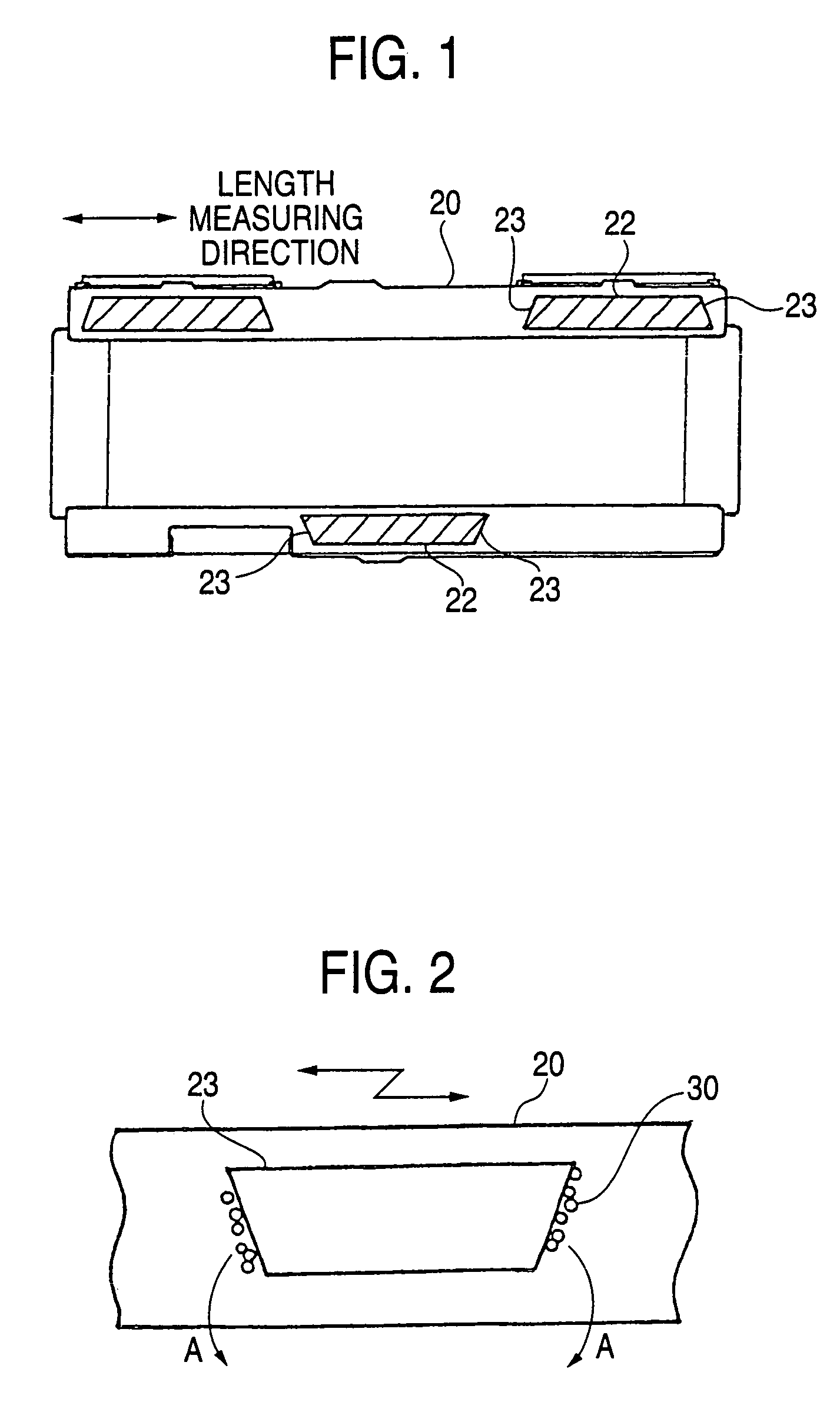
[0028]According to the present invention, in a linear scale similar to that of the example of the related art shown in FIG. 6 through FIG. 8, as shown by a constitution of an essential portion in FIG. 1, a slide shoe 22 of a slider 20 is formed with inclined faces 23 inclined outwardly for excluding the foreign matter on a sliding guide face 11 at both ends of the slide shoe 22 in a direction of moving the slide shoe 22.

[0029]According to the constitution, as shown by FIG. 2, by sliding the slide shoe 22, a foreign matter 30 accumulated on the sliding guide face 11 can be swept out to outside as shown by an arrow mark A.

second embodiment

[0030]Next, a detailed explanation will be given of the present invention.

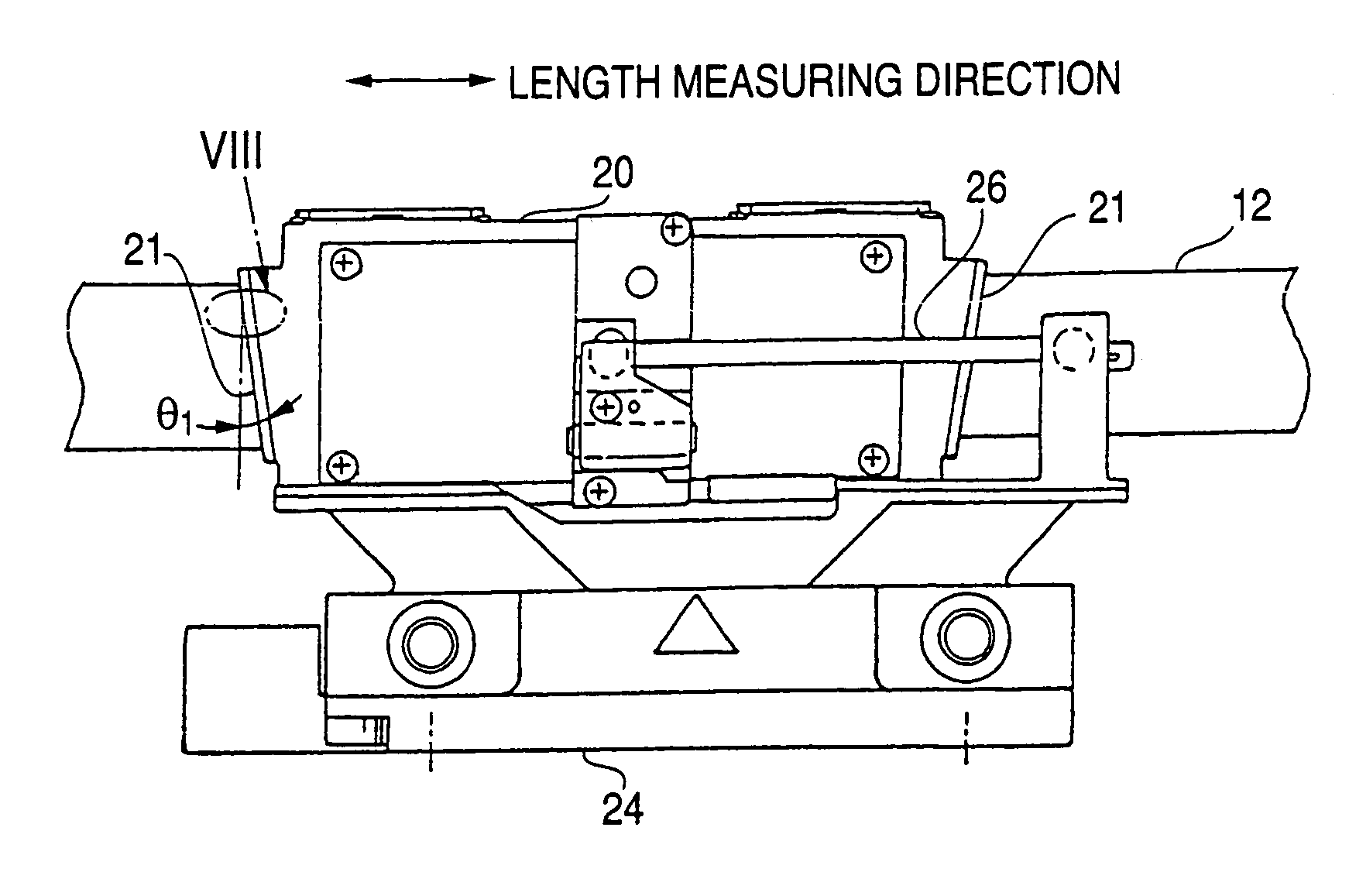
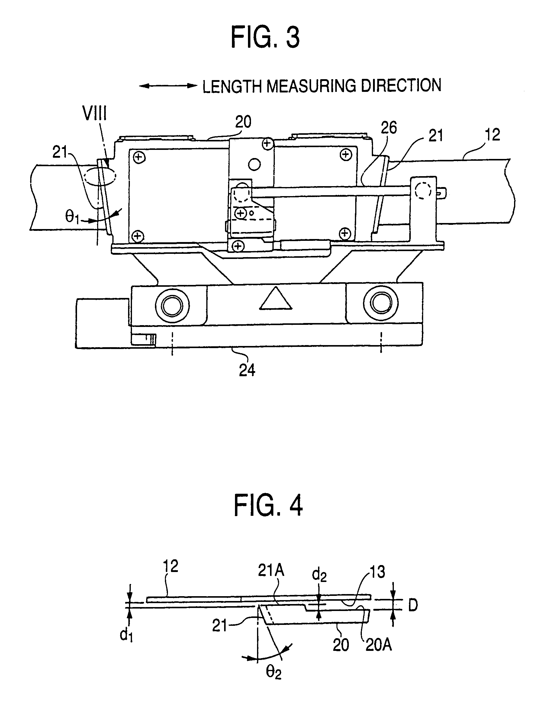
[0031]According to the embodiment, as shown by FIG. 3, a slider 20 is formed with inclined faces 21 having an angle of θ1 for excluding the foreign matter on a scale face 13 at both ends of the slider 20 in a moving direction.

[0032]As shown by FIG. 4, the inclined face 21 is provided not only in a plane direction of the scale but also a side face direction thereof by an angle θ2.

[0033]Further, as shown in FIG. 5 in details, a face 21A on a side of the scale of the inclined face 21 is made to be more proximate to the scale face 13 than an interval D between a sensor face 20A of the slider 20 and the scale face 13 by an amount of d2.

[0034]In this way, in a state of adhering the foreign matter onto the scale face 13, by sliding the slider 20 at the portion, the foreign matter can be removed.

[0035]According to the embodiment, the inclined face 21 is made to be more proximate to the scale face 13 than the interval ...


PUM


Abstract

A slider or a slide shoe for maintaining an interval between a scale and the slider is provided with inclined faces for excluding a foreign matter on a scale face or a sliding guide face at both ends of the slider in a moving direction thereof or at both ends of the slide shoe.

Description

BACKGROUND OF THE INVENTION[0001]1. Field of the Invention[0002]The present invention relates to a length measuring apparatus having a scale extended in a length measuring direction and a slider including a sensor moving in the length measuring direction along the scale relative thereto in a state of maintaining a predetermined interval between the scale and the slider. Particularly, the present invention relates to a length measuring apparatus preferably used in a linear scale or a length measuring unit and promoting reliability by avoiding an obstacle in mechanism against invasion of a foreign matter from outside.[0003]2. Description of the Related Art[0004]In a measuring apparatus of a linear scale or the like, there are guide mechanisms for ensuring a clearance between a scale and a detecting sensor by rolling (bearing) and sliding.[0005]An example of a linear scale adopting the latter is shown by FIG. 6 (sectional view), FIG. 7 (right side view of a slider portion) and FIG. 8 (...

Claims


Application Information

Patent Timeline
IPC IPC(8): G01B5/04G01D5/245G01D5/347G01D5/36G01D11/24G01D21/00
CPCG01D11/245G01D5/34753
Inventor KODAMA, KAZUHIKOISHIKAWA, YUTAKA
Owner MITUTOYO CORP
Why Eureka
Try Eureka