Induction heating stress improvement

a technology of induction heating and stress improvement, which is applied in the direction of heat treatment apparatus, magnetic bodies, furnaces, etc., can solve the problems of inability to estimate inability to effectively work with the force of the nozzle, and inability to measure the temperature of the fluid flowing out of the annular clearance, etc., to achieve stable cooling effect, enhance cooling effect, and promote cooling

a technology of induction heating and stress improvement, which is applied in the direction of heat treatment apparatus, magnetic bodies, furnaces, etc., can solve the problems of inability to estimate inability to effectively work with the force of the nozzle, and inability to measure the temperature of the fluid flowing out of the annular clearance, etc., to achieve stable cooling effect, enhance cooling effect, and promote cooling

US20060197638A1Active Publication Date: 2006-09-07HITACHI-GE NUCLEAR ENERGY LTD

Image

  • Induction heating stress improvement
  • Induction heating stress improvement
  • Induction heating stress improvement

Examples


Embodiment Construction

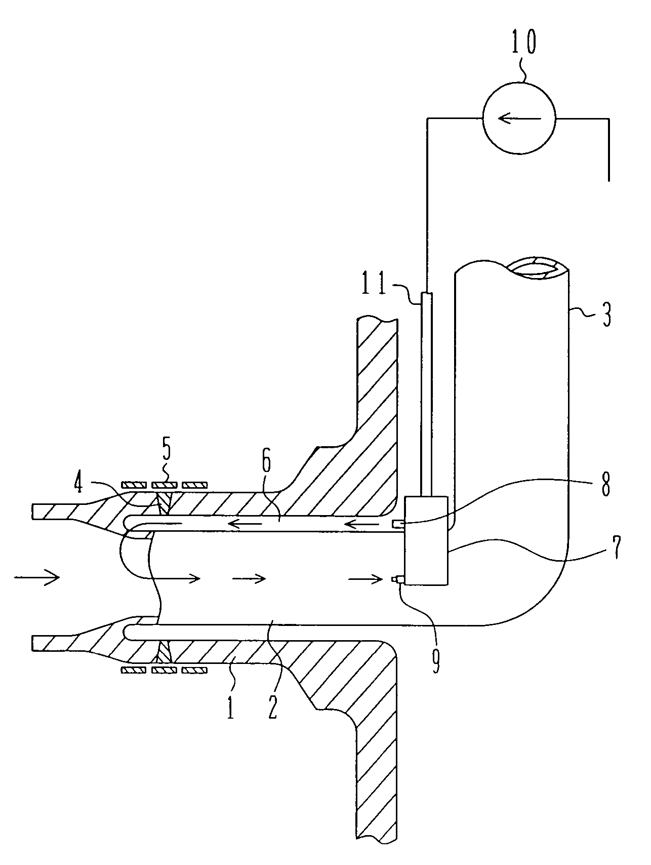
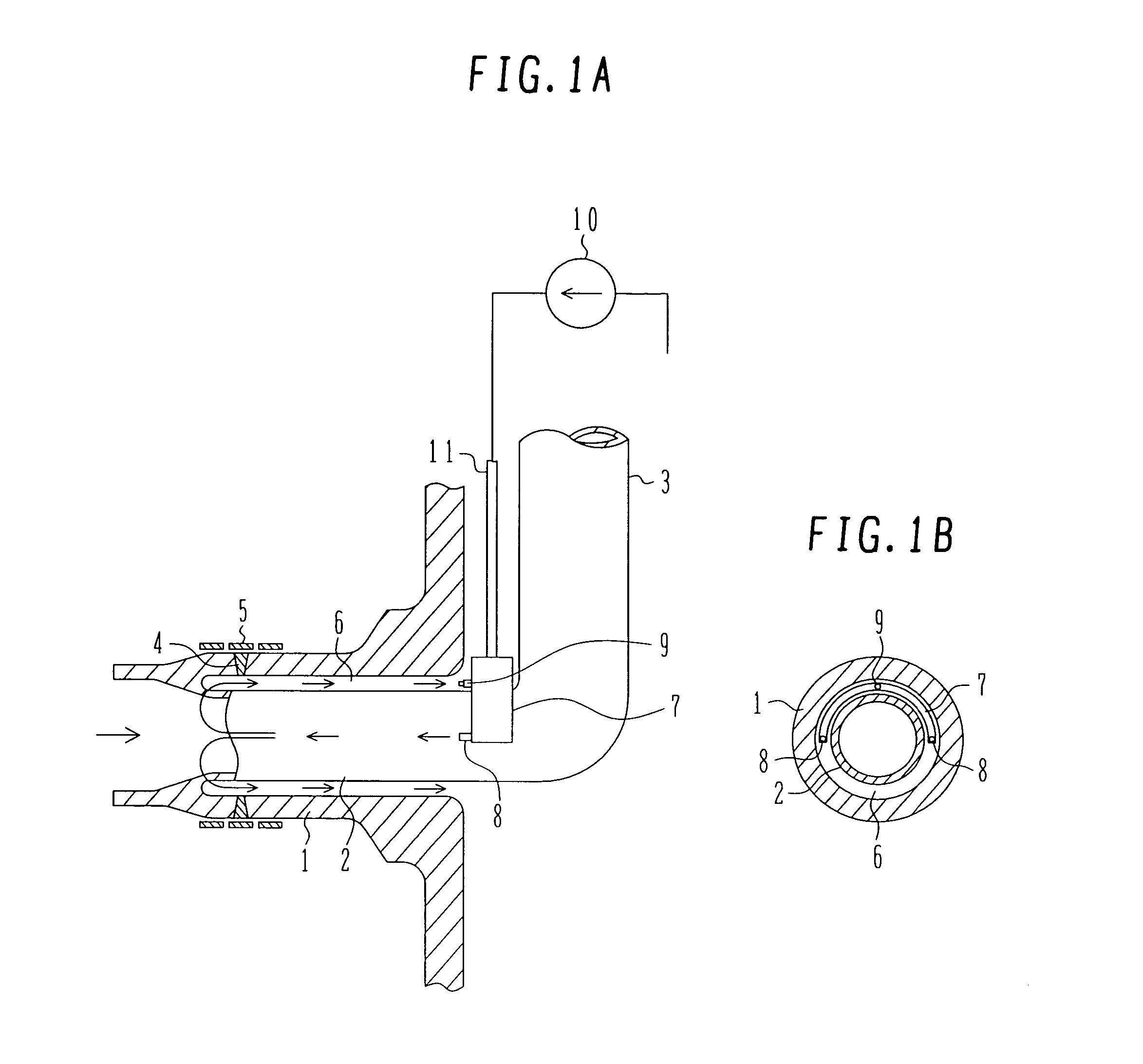
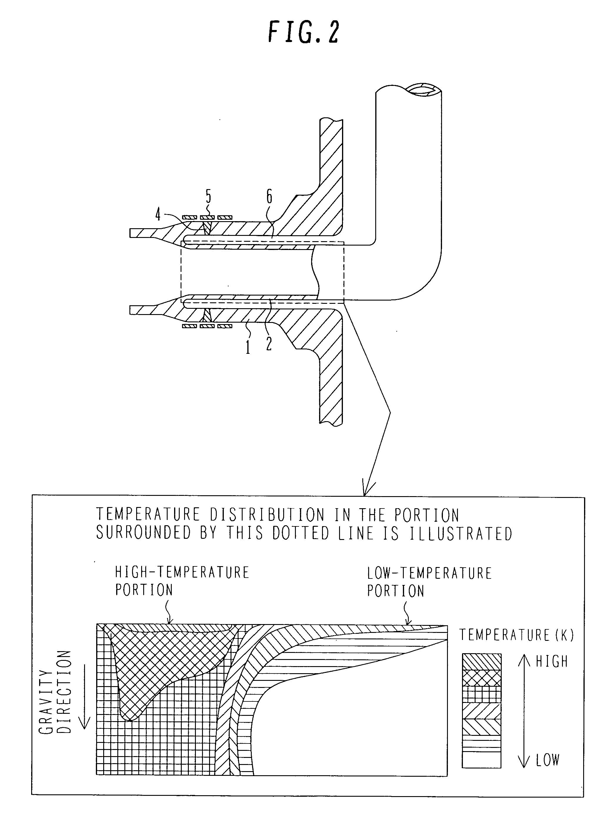
[0047] A piping cooling technique in IHSI method according to the present invention will be described with reference to FIG. 1. FIG. 1 is a constructional view of a recirculation inlet according to an embodiment of the present invention. The recirculation inlet comprises an N2 nozzle 1, a thermal sleeve 2 therein arranged, and a riser tube 3 serving as a jet pump and connected to the thermal sleeve 2. At a welding portion 4 in the N2 nozzle 1, the residual stress can be relaxed by the execution of IHSI method. This enables enhancement of the safety of nuclear power. The IHSI method is a method for heating the surface of the outer surface of the piping by a heater 5 provided in the outer surface of the piping and cooling the inner surface of the piping by water in the piping, whereby residual stress is relaxed by a thermal gradient in the cross-section of the piping. When the piping is of a pure straight pipe, the inner surface of the piping is sufficiently cooled, and there is no pr...


PUM

PropertyMeasurementUnit
angle of tiltaaaaaaaaaa
saturation temperatureaaaaaaaaaa
pressureaaaaaaaaaa

Abstract

In implementing an induction heating stress improvement (IHSI) method in a nuclear plant, cooling characteristic with respect to the inner surface of piping is improved by appropriate structure / layout of nozzles, and further, the cooling effect when applying IHSI to a real machine is verified by installing a thermometer, as well as air in the portion subjected to IHSI is removed by heating the piping prior to the execution of IHSI.

Description

BACKGROUND OF THE INVENTION [0001] 1. Field of the Invention [0002] The present invention relates to an induction heating stress improvement method (hereinafter abbreviated as “IHSI” method) in a primary loop recirculation piping (hereinafter abbreviated as “PLR” piping) of a nuclear power plant. [0003] 2. Description of the Related Art [0004] As an example of conventional IHSI method for a double metal, there is a method disclosed in JP, A 2-282428. In this conventional art, water flows are alternately spouted into an annular space, and the nozzle outer surface surrounding the annular space is heated to give a temperature difference to the nozzle wall, whereby residual stress is relaxed. [0005] Conventional inventions, however, have involved a problem in that they have indeed exerted an enhanced cooling effect but have been incapable of verifying a cooling effect when applying IHSI to an actual machine. Particularly in a recirculation inlet nozzle (hereinafter referred to as an “N2...

Claims


Application Information

Patent Timeline
07 Sep 2006
Publication
US20060197638A1
IPC
H01F1/00
CPC
C21D1/42; C21D9/08; C21D9/50; C21D11/00; Y02P10/25
Inventors
TAKAHASHI, SHIRO; SHIINA, KOUJI