Bolt tightening method and bolt tightening apparatus

a bolt and apparatus technology, applied in the direction of apparatus for force/torque/work measurement, static/dynamic balance measurement, instruments, etc., can solve the problems of unstable effect, low effective bolt axial force acting on the fastened member, and not being so easy to apply the seating-point angle method to such facilities or apparatuses

Active Publication Date: 2006-10-05
MAZDA MOTOR CORP
View PDF4 Cites 34 Cited by
  • Summary
  • Abstract
  • Description
  • Claims
  • Application Information

AI Technical Summary

Benefits of technology

[0019] The present invention has been devised in view of the above-described things, and an object of the present invention is to provide a method and an apparatus for tightening bolts, in which the torque+angle method is adopted basically and the scatter of the bolt axial force du

Problems solved by technology

However, when the conventional torque+angle method is applied to a case where the properties have bent properties, like C2 or C2′ in the figure, comprising an initial bolt tightening stage I having a smaller torque gradient and a late bolt tightening stage II having a larger torque (torque gradient being expressed in terms of the ratio of an additional tightening torque exerted on the bolt to its additional turning angle), there is a

Method used


Image

  • Bolt tightening method and bolt tightening apparatus
  • Bolt tightening method and bolt tightening apparatus
  • Bolt tightening method and bolt tightening apparatus

Examples


Embodiment Construction

[0055] Hereinafter, preferred embodiments of the present invention will be described referring to the accompanying drawings.

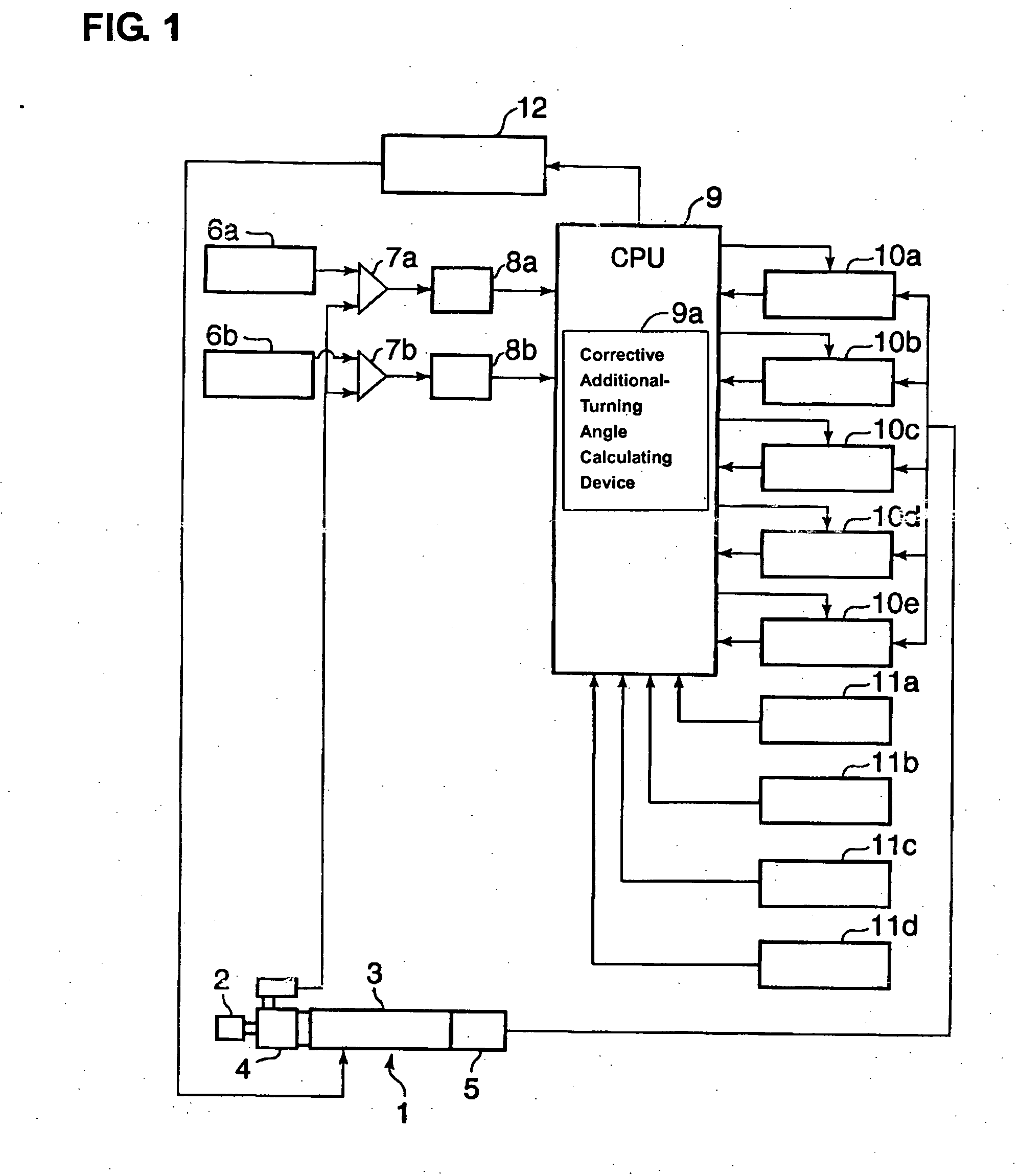
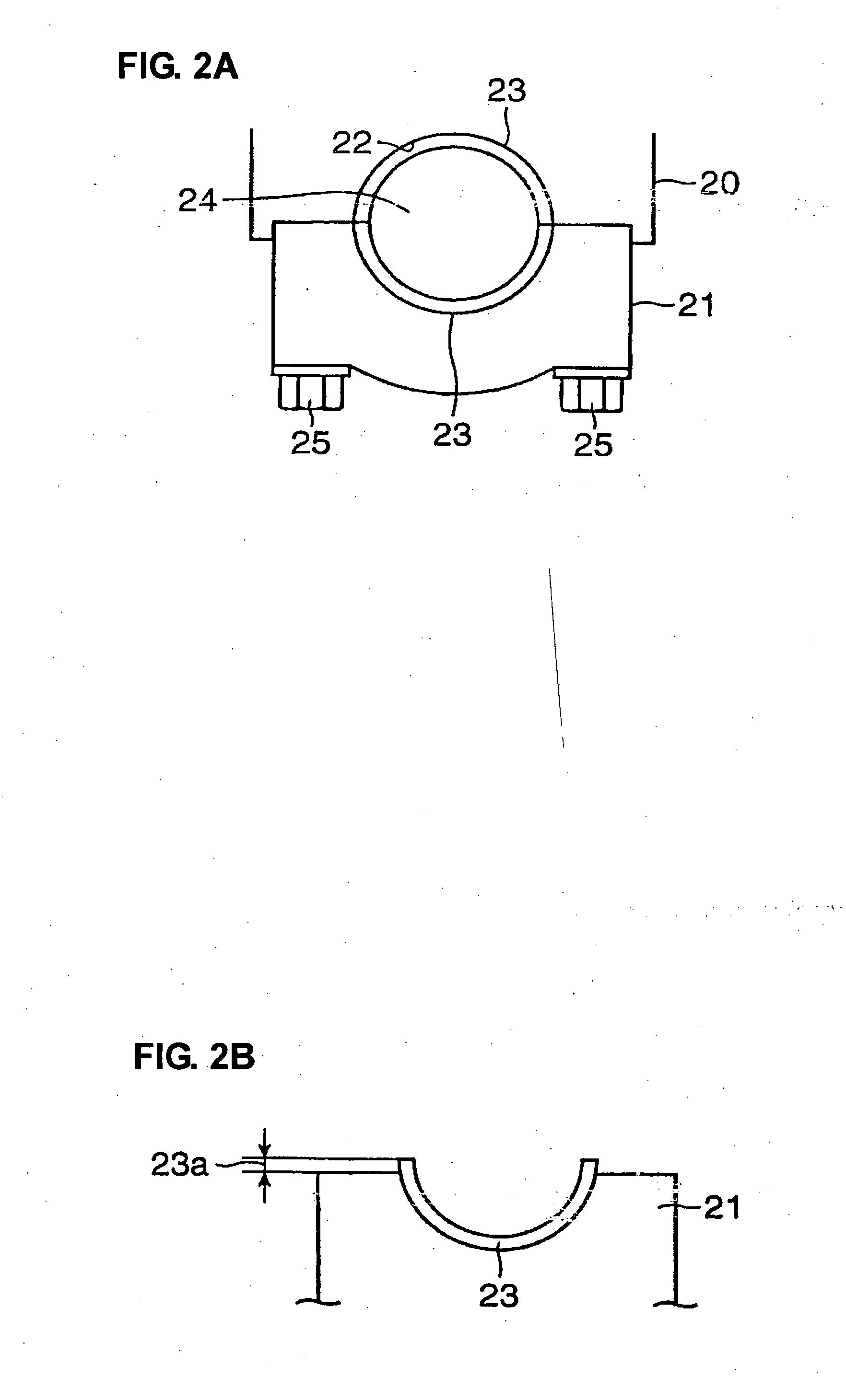
[0056]FIG. 1 shows a bolt tightening apparatus according to a fist embodiment of the present invention. This apparatus, whose constitution will be described in detail below, is suitable, for example, when fastening a mounting body 20 and a bearing cap 21 of a cylinder body of an engine, which is shown in FIG. 2A, by tightening a bolt 25.

[0057] The mounting body 20 and bearing cap 21 form a bearing of a crank shaft 24. These members 20, 21 have a half-circle shaped bore respectively so as to form a bearing bore 22 between them. A pair of half shell sections 23 as a half-shell bearing are fitted in the bearing bore 22 around the crank shaft 24. Each half shell section 23 has a half-cylindrical shape, like being formed by splitting a cylindrical member into halves. The mounting body 20 and the bearing cap 21 are fastened with the half shell sections 23 and crank...


PUM

PropertyMeasurementUnit
Angleaaaaaaaaaa
Deformation enthalpyaaaaaaaaaa
Torqueaaaaaaaaaa

Abstract

After it is tightened with a snug torque TA, a bolt is tuned by a total turning angle θS equivalent to the sum of an initial-set turning angle θA and a corrective additional-turning angle (θBC). The corrective additional-turning angle (θBC) is the sum of a first corrective additional-turning angle θB and a second corrective additional-turning angle θC, the first corrective additional-turning angle θB being to compensate for a situation where a bolt turning angle θ22 corresponding to the snug torque θA on an extension line of the bolt tightening torque properties C2 in a late tightening stage II is different from a bolt turning angle θ11 corresponding to the actual snug torque TA, the second corrective additional-turning angle θC being to compensate for a decrease of an effective bolt axial force that is caused by an existence of the initial tightening stage I.

Description

BACKGROUND OF THE INVENTION [0001] The present invention relates to a method and an apparatus for tightening bolts. In particular, it relates to those that is suitably applicable to a bolt having bolt tightening torque properties, in which a torque gradient expressed in terms of the ratio of an additional tightening torque exerted on a bolt to its additional turning angle has a first torque gradient in an initial bolt tightening stage and a second torque gradient in a late bolt tightening stage subsequent to the initial bolt tightening stage, a magnitude of the second torque gradient being greater than that of the first torque gradient. [0002] A bolt tightening method in which at first the bolt is tightening until a bolt tightening torque reaches (becomes) a predetermined snug torque and subsequently the bolt is turned by a predetermined initial-set turning angle (hereinafter, referred to as “torque+angle method”) is well known. [0003] This conventional torque+angle method (snug tor...

Claims


Application Information

Patent Timeline
IPC IPC(8): B23Q5/00B25B23/14B23Q17/00
CPCB23P19/066Y10T29/49766Y10T29/49767B25B23/14
Inventor MAKIMAE, TATSUMIFUJII, YUTAKASHINAGAWA, HIROSHI
Owner MAZDA MOTOR CORP
Why Eureka
Try Eureka