[0012]For the treatment apparatus described in United States
Patent Application 2004 / 0024300 A1, a mechanism for a rotating gantry is doubled up, the treatment apparatus is mechanically complicated, and its overall cost is increased. In addition, the treatment apparatus described in United States Patent Application 2004 / 0024300 A1 is an X-ray treatment apparatus. Thus, when the technique based on United States Patent Application 2004 / 0024300 A1 is introduced in a
proton treatment apparatus as it is, the proton treatment apparatus will disadvantageously have a limited imaging range. The reason that the imaging range is limited is that an irradiation nozzle apparatus for the proton treatment apparatus is larger than that for the X-ray treatment apparatus.
[0013]An object of the present invention is to provide, for obtaining a fine beam in a
beam scanning irradiation method, a particle beam treatment apparatus and an irradiation nozzle apparatus which is adapted to ensure a space for installation of a beam transport chamber in the irradiation nozzle apparatus, suppress an increase in the cost of the particle beam treatment apparatus, and ensure a necessary imaging range.
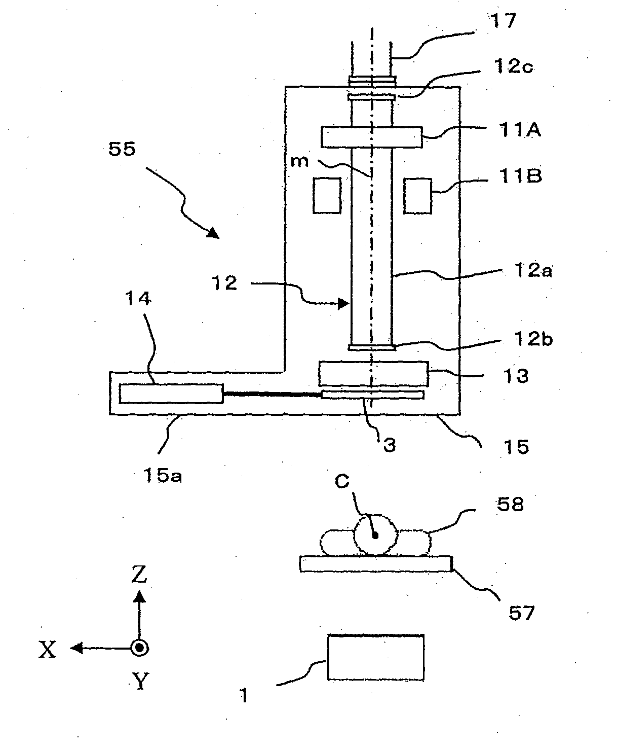
[0014]To accomplish the aforementioned object, according to the present invention, an X-ray tube is located outside a scanning type irradiation nozzle apparatus that includes scanning magnets, whereas an X-ray
detector is located inside the scanning type irradiation nozzle apparatus. In a conventional structure, an X-ray tube is located inside an irradiation nozzle apparatus and an X-ray detector is located outside that. According to the present invention, the X-ray detector, especially that including a
flat panel detector is smaller in thickness in the direction of a beam axis and is simpler in structure than that of the X-ray tube. This makes it possible to ensure a space for installation of the beam transport chamber in the irradiation nozzle apparatus, and increase the length of the beam transport chamber in the apparatus compared with the conventional structure. It is, therefore, possible to suppress scattering of the beam caused by air during transport of the beam and reduce the
diameter of the beam compared with the conventional structure.
[0015]In addition, since the X-ray detector is smaller in thickness in the direction of the beam axis and is simpler in structure than that of the X-ray tube, high degree of freedom as to where to arrange the X-ray detector is provided. Thus, the X-ray tube can be installed in a position shifted to the downstream side of the irradiation nozzle apparatus compared with a position at which a conventional X-ray tube is located. For example, the scanning type irradiation nozzle apparatus may include a
beam monitor (e.g., beam
dose monitor) arranged in a position on the downstream side of the scanning magnets and the beam transport chamber with respect to the direction in which the beam propagates. In this case, the X-ray detector may be installed in a position on a further downstream side relative to the
beam monitor. This makes it possible to ensure a space for installation of the beam transport chamber in such a manner that the beam transport chamber can be located at the optimum position in the irradiation nozzle apparatus. Furthermore, it is possible to increase the length of the beam transport chamber, thereby reducing the diameter of the beam compared with the conventional structure.
[0016]In addition, only replacing the positions of the X-ray tube and the X-ray detector with each other is performed, thereby making it possible to suppress an increase in the cost of the particle beam treatment apparatus and ensure a necessary imaging range.
[0017]According to the present invention, it is possible to ensure a space for installation of the beam transport chamber in the irradiation nozzle apparatus. As a result, while the length of the irradiation nozzle apparatus is as long as that of the conventional one, the irradiation nozzle apparatus may include the beam transport chamber whose length is longer than the conventional structure. Thus, it is possible to reduce the diameter of the beam compared with the conventional structure. In addition, it is possible to suppress an increase in the cost of the particle beam treatment apparatus and ensure a necessary imaging range.

