Fluorescent illumination device

a fluorescent light and illumination device technology, applied in semiconductor devices for light sources, point-like light sources, light and heating apparatuses, etc., can solve the problems of high cost of neon light package and ship, limited visible color spectrum, and extremely awkward initial handling, installation, and/or replacement, etc., and achieve the effect of increasing the cost or complexity of the illumination devi

Inactive Publication Date: 2007-03-20
LUMINII PURCHASER LLC
View PDF32 Cites 119 Cited by
  • Summary
  • Abstract
  • Description
  • Claims
  • Application Information

AI Technical Summary

Benefits of technology

[0007]In any event, a problem with illumination devices using LEDs is that the available visible color spectrum is limited by the finite availability of LED colors. There is thus a need for an illumination device that allows for emission of light in colors that cannot ordinarily be achieved by use of LEDs alone without significant increase in cost or complexity of the illumination device.

Problems solved by technology

Because of the fragility and heavy weight, primarily due to its supporting infrastructure, neon lighting is expensive to package and ship.
Moreover, it is extremely awkward to initially handle, install, and / or replace.
However, the twin attributes of neon lighting, uniformity and brightness, have proven to be difficult obstacles to overcome as such attempts to simulate neon lighting have largely been stymied by the tradeoffs between light distribution to promote the uniformity and brightness.
In any event, a problem with illumination devices using LEDs is that the available visible color spectrum is limited by the finite availability of LED colors.

Method used


Image

  • Fluorescent illumination device
  • Fluorescent illumination device
  • Fluorescent illumination device

Examples


Embodiment Construction

[0019]The present invention is an illumination device for simulating neon lighting through use of fluorescent dyes, thus allowing for emission of light in colors that cannot ordinarily be achieved by use of LEDs alone without significant increase in cost or complexity of the illumination device.

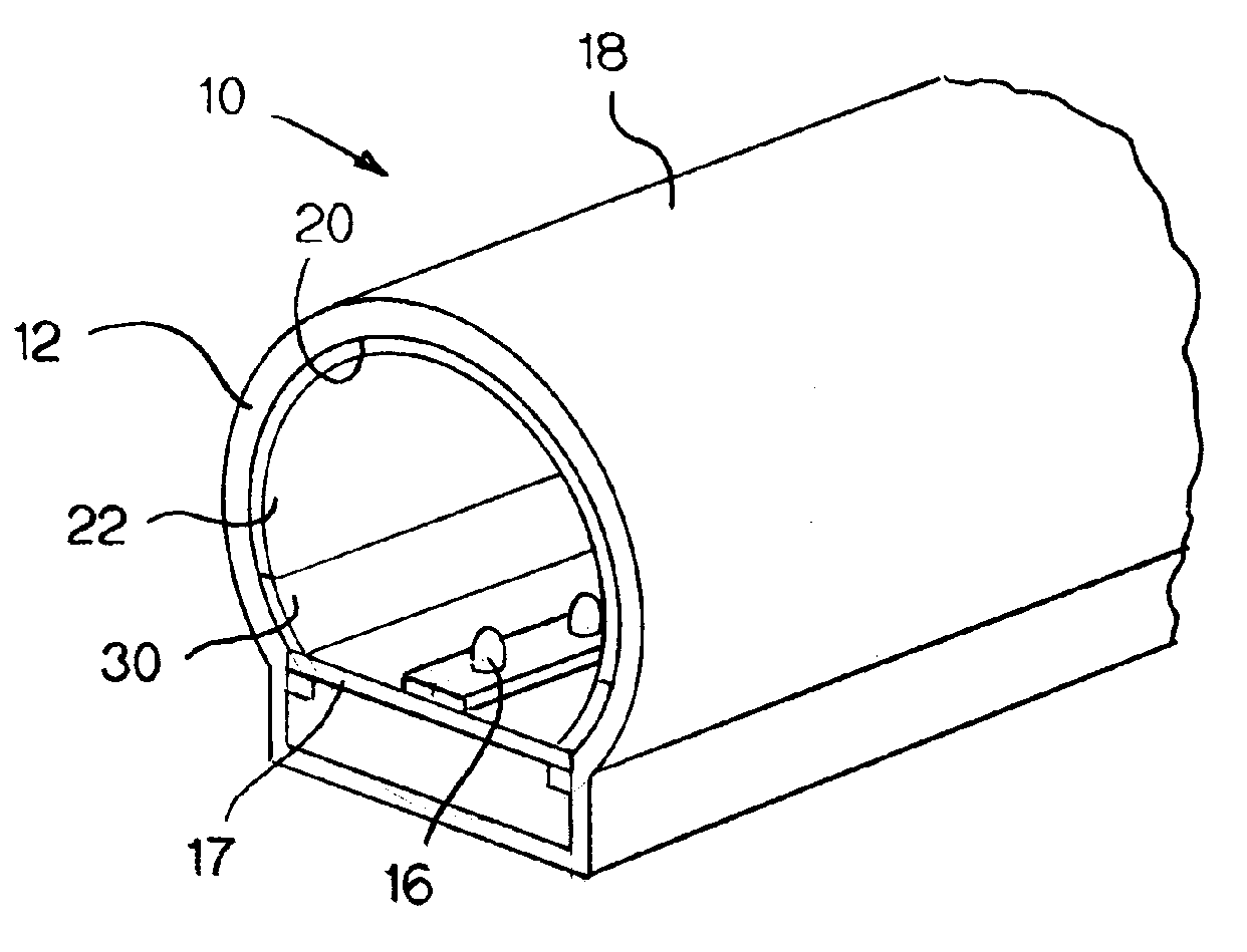
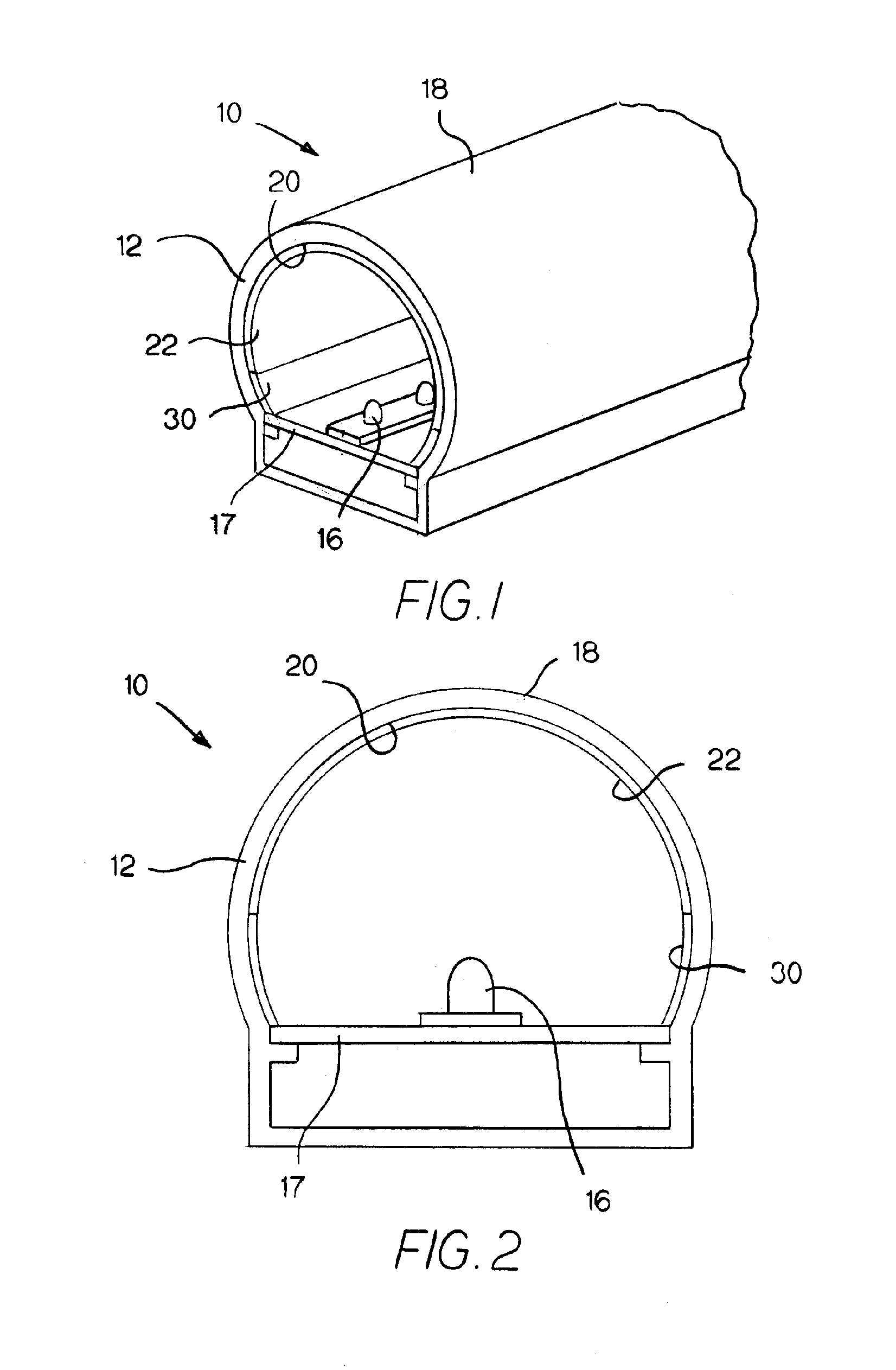
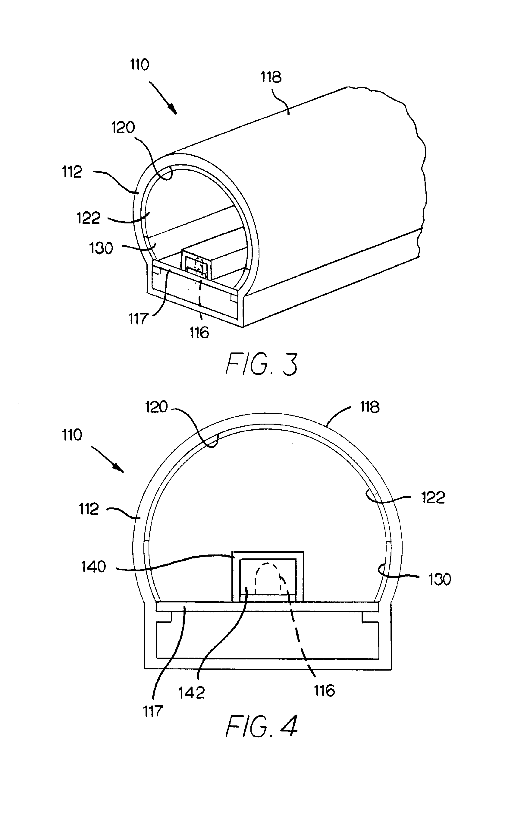
[0020]An exemplary illumination device 10 made in accordance with the present invention is illustrated in FIGS. 1–2. The illumination device 10 is generally comprised of an elongated diffusing member 12 and a light source 16. In this exemplary embodiment, the diffusing member 12 has a substantially hollow tube construction, with an external surface 18 serving as a light-emitting surface and an interior surface 20 that serves as a light-receiving surface. Light entering the diffusing member 12 from the light source 16 is scattered within the diffusing member 12 so as to exit with diffused distribution along the light-emitting surface 18.

[0021]As best shown in FIG. 2, the light source 16 and as...


PUM


Abstract

An illumination device for simulating neon or similar lighting uses fluorescent dyes, thus allowing for emission of light in colors that cannot ordinarily be achieved by use of LEDs alone. Such an illumination device is generally comprised of an elongated diffusing member enclosing a string of continuously mounted LEDs. An intermediate light-transmitting medium including a predetermined combination of one or more fluorescent dyes is interposed between the light source and the diffusing member, such that light from the LEDs is partially absorbed by each of the fluorescent dyes, and a lower-energy light is then emitted from each of the fluorescent dyes and into the light-receiving surface of the diffusing member, producing a substantially uniform light along the light-emitting surface of the diffusing member with perceived a color different than that of the LEDs.

Description

CROSS-REFERENCE TO RELATED APPLICATIONS[0001]The present application is a continuation-in-part of U.S. Utility application Ser. No. 10 / 455,639 filed Jun. 5, 2003, which itself is a continuation-in-part of U.S. Utility application Ser. No. 09 / 982,705 filed Oct. 18, 2001 (now U.S. Pat. No. 6,592,238), the entire disclosures of which are incorporated herein by reference.BACKGROUND OF THE INVENTION[0002]The present invention relates to an illumination device, an illumination device using high-intensity, low-voltage light sources and ideally adapted for lighting, signage and advertising uses.[0003]Neon lighting, which is produced by the electrical stimulation of the electrons in a low-pressure neon gas-filled glass tube, has been a main stay in advertising and for outlining channel letters and building structures for many years. A characteristic of neon lighting is that the tubing encompassing the gas has an even glow over its entire length irrespective of the viewing angle. This charact...

Claims


Application Information

Patent Timeline
Patent Type & Authority Patents(United States)
IPC IPC(8): F21V23/02
CPCF21S4/003F21V9/16F21Y2103/003F21Y2101/02F21S4/20F21Y2103/10F21Y2115/10F21V9/38F21V13/08
Inventor CLEAVER, MARK J.HULSE, GEORGE R.
Owner LUMINII PURCHASER LLC
Why Eureka
Try Eureka