Machine and method for welding rails of a track

Inactive Publication Date: 2006-11-23
FRANZ PLASSER BAHNBAUMASCHINEN IND GMBH
View PDF18 Cites 17 Cited by
  • Summary
  • Abstract
  • Description
  • Claims
  • Application Information

AI Technical Summary

Benefits of technology

[0006] It is accordingly an object of the present invention to provide a machine of the specified kind for welding rails of a track which overcomes the disadvantages of the heretofore-known machines of this general type and which enables the rails to be gripped by the rail pulling device in a simplified manner.

Problems solved by technology

This is done by driving wedges between the base plates and the rail base in a laborious manner.

Method used


Image

  • Machine and method for welding rails of a track
  • Machine and method for welding rails of a track

Examples


Embodiment Construction

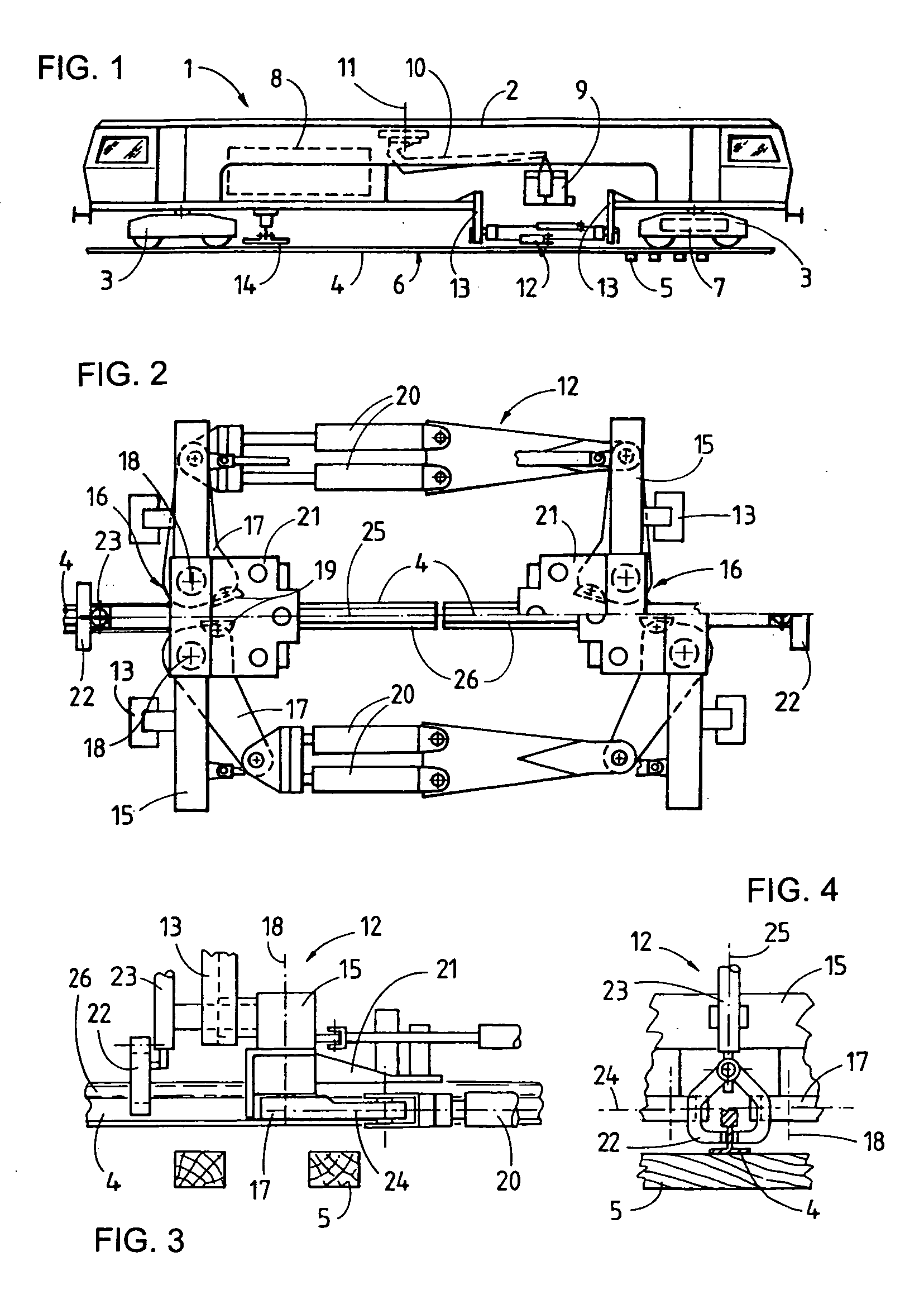
[0030] Referring now to the drawing in detail and first, particularly, to FIG. 1 thereof, there is shown a welding machine 1 which has a bridge-like machine frame 2. With the aid of on-track undercarriages 3, arranged at the ends, and a motive drive 7, the machine 1 is mobile on a track 6. The latter comprises rails 4 and ties 5 and extends in a longitudinal direction. A central power plant 8 including a drive motor, hydraulic pumps and a generator is provided for delivering the energy required for operation of the machine 1.

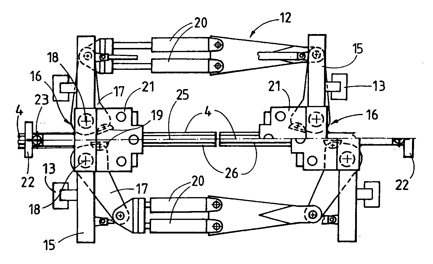
[0031] Centrally between the two on-track undercarriages 3, there is disposed an electric flash-butt welding unit 9, which is connected to a telescopically extendable and vertically adjustable boom 10 which, in turn, is fastened to the machine frame 2 and rotatable about a vertical axis 11. Arranged underneath the flash-butt welding unit 9 is a rail pulling device 12 which is mounted in guides 13 connected to the machine frame 2. Situated in the region of one o...


PUM

PropertyMeasurementUnit
symmetryaaaaaaaaaa
distanceaaaaaaaaaa
forceaaaaaaaaaa

Abstract

A machine for welding the rails of a track includes a rail pulling device that grips the rail ends and pulls them together so that they can be welded to one another. Two rail clamps provided for gripping the rails are fastened to the rail pulling device. The rail clamps are each vertically adjustable in their position relative to the rail pulling device by way of a respective adjustment drive in a direction extending perpendicularly to a pulling device plane formed by hydraulic drives of the rail pulling device. With this, the rails can be lifted from ties in a simple manner in order to enable the clamping members of the rail pulling device to grip the rails.

Description

CROSS-REFERENCE TO RELATED APPLICATION [0001] This application claims the priority, under 35 U.S.C. § 119, of European patent application No. 05 104 174.7, filed May 18, 2005, which is herewith incorporated by reference in its entirety. BACKGROUND OF THE INVENTION [0002] 1. Field of the Invention [0003] The present invention relates, in general, to a machine for welding rails of a track, including a machine frame mobile on the track, a rail pulling device comprising clamping members and hydraulic drives, and a welding unit. The invention further pertains to a method of welding rails of a track. [0004] 2. Description of the Related Art [0005] Machines of this type for welding rails of a track have become known, for example, from U.S. Pat. No. 5,136,140, from European patent publication EP 0 326 794, or from U.S. Pat. No. 4,929,816. The welding operation is assisted by a rail pulling device which pulls the clamped rail ends towards one another with great force to a distance required f...

Claims


Application Information

Patent Timeline
Patent Type & Authority Applications(United States)
IPC IPC(8): H05B1/00
CPCB23K11/04E01B29/46B23K2201/26B23K2101/26
Inventor THEURER, JOSEFLICHTBERGER, BERNHARD
Owner FRANZ PLASSER BAHNBAUMASCHINEN IND GMBH
Why Eureka
Try Eureka