Method to determine phase and/or amplitude between interfering, adjacent x-ray beams in a detector pixel in a talbot interferometer

a technology of interferometer and detector pixel, which is applied in the direction of radiation diagnostic diaphragm, instruments, tomography, etc., can solve the problems of requiring the displacement of one of the gratings, the method is very complicated, and the sampling measurement time is relatively long

Active Publication Date: 2010-03-25
SIEMENS HEALTHCARE GMBH
View PDF0 Cites 51 Cited by
  • Summary
  • Abstract
  • Description
  • Claims
  • Application Information

AI Technical Summary

Benefits of technology

[0010]An object of the present invention is to provide a method to measure the intensity curve at a detector pixel relative to the displacement of the upstream grating in a Talbot interferometer that delivers the desired information (such as phase, amplitude or intensity median) in a simplified manner.

Problems solved by technology

A significant problem in this type of measurement is that a sequential displacement of one of the gratings must occur.
Such a method is very complicated and generates relatively long sampling measurement times, so it is difficult to integrate these measurement procedures into practical applications, in particular into fast CT scans with a rotating gantry.
However, such an arrangement is very complicated and, at the present time, is not suitable for designing the detector in quantity, due to cost reasons.
The difficulties that result due to such a sequential measurement correspond to the difficulties that occur in phase contrast measurement.

Method used


Image

  • Method to determine phase and/or amplitude between interfering, adjacent x-ray beams in a detector pixel in a talbot interferometer
  • Method to determine phase and/or amplitude between interfering, adjacent x-ray beams in a detector pixel in a talbot interferometer
  • Method to determine phase and/or amplitude between interfering, adjacent x-ray beams in a detector pixel in a talbot interferometer

Examples


Embodiment Construction

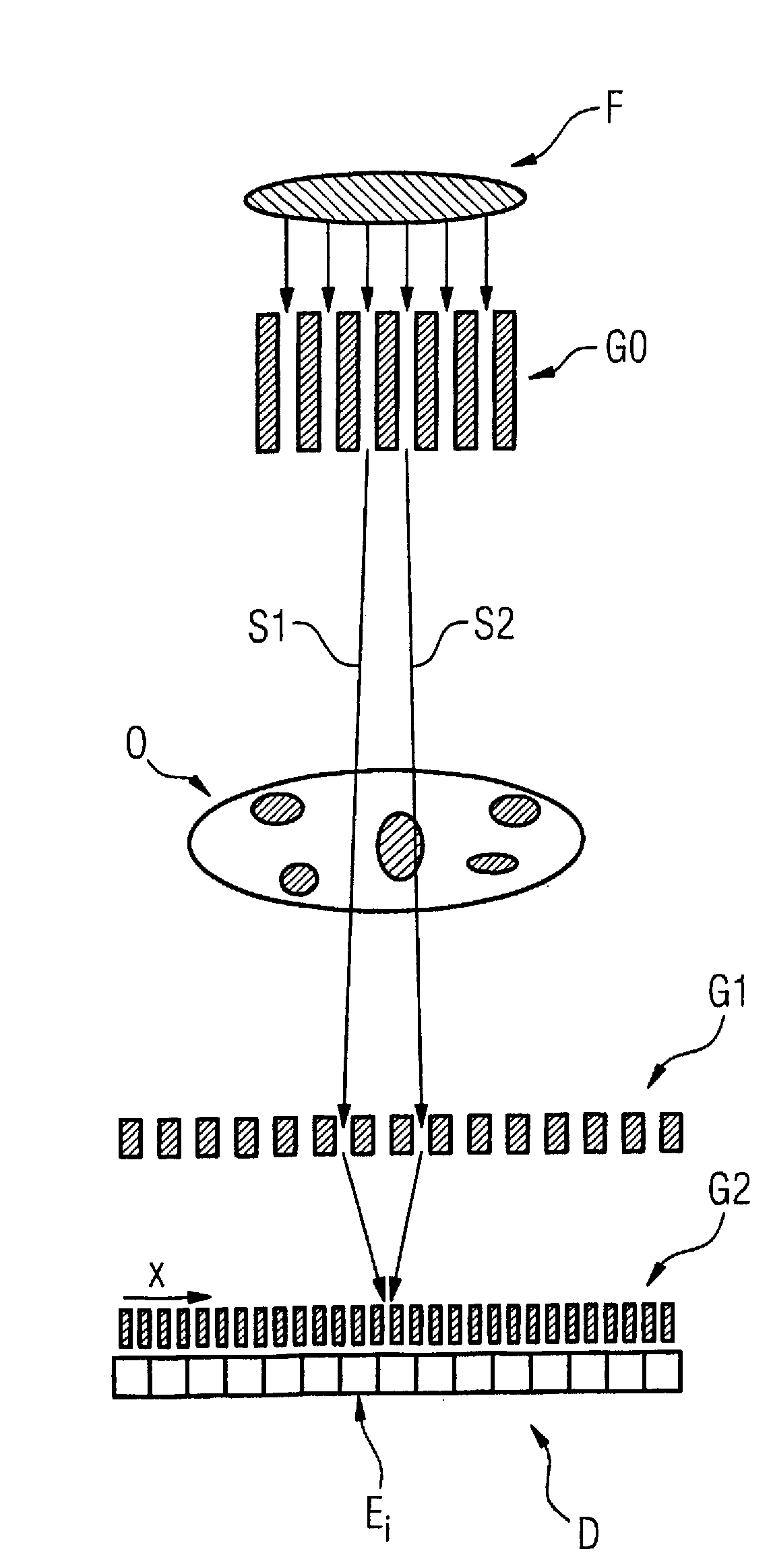
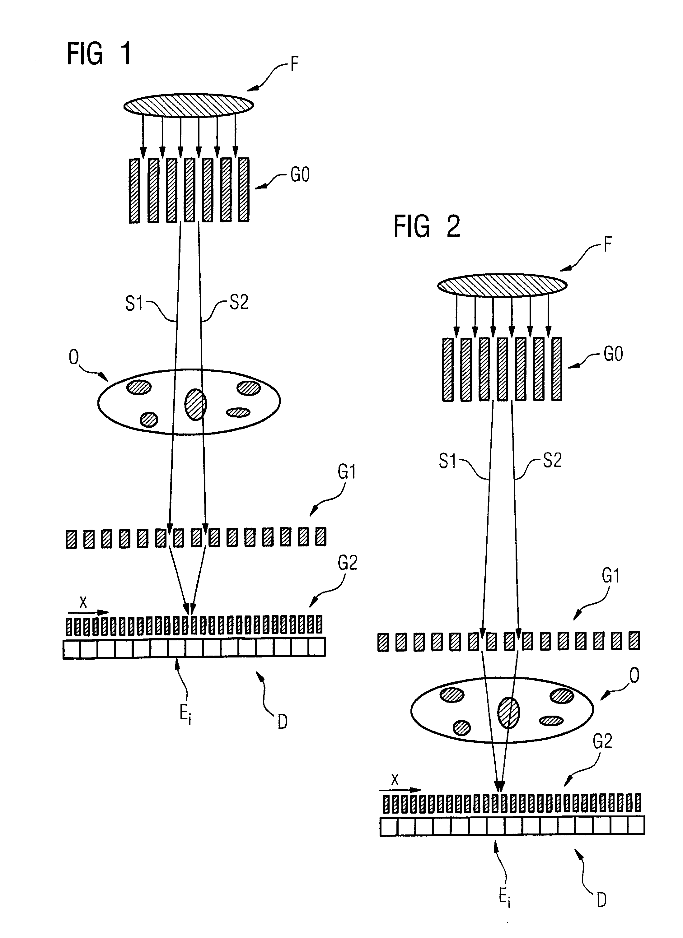
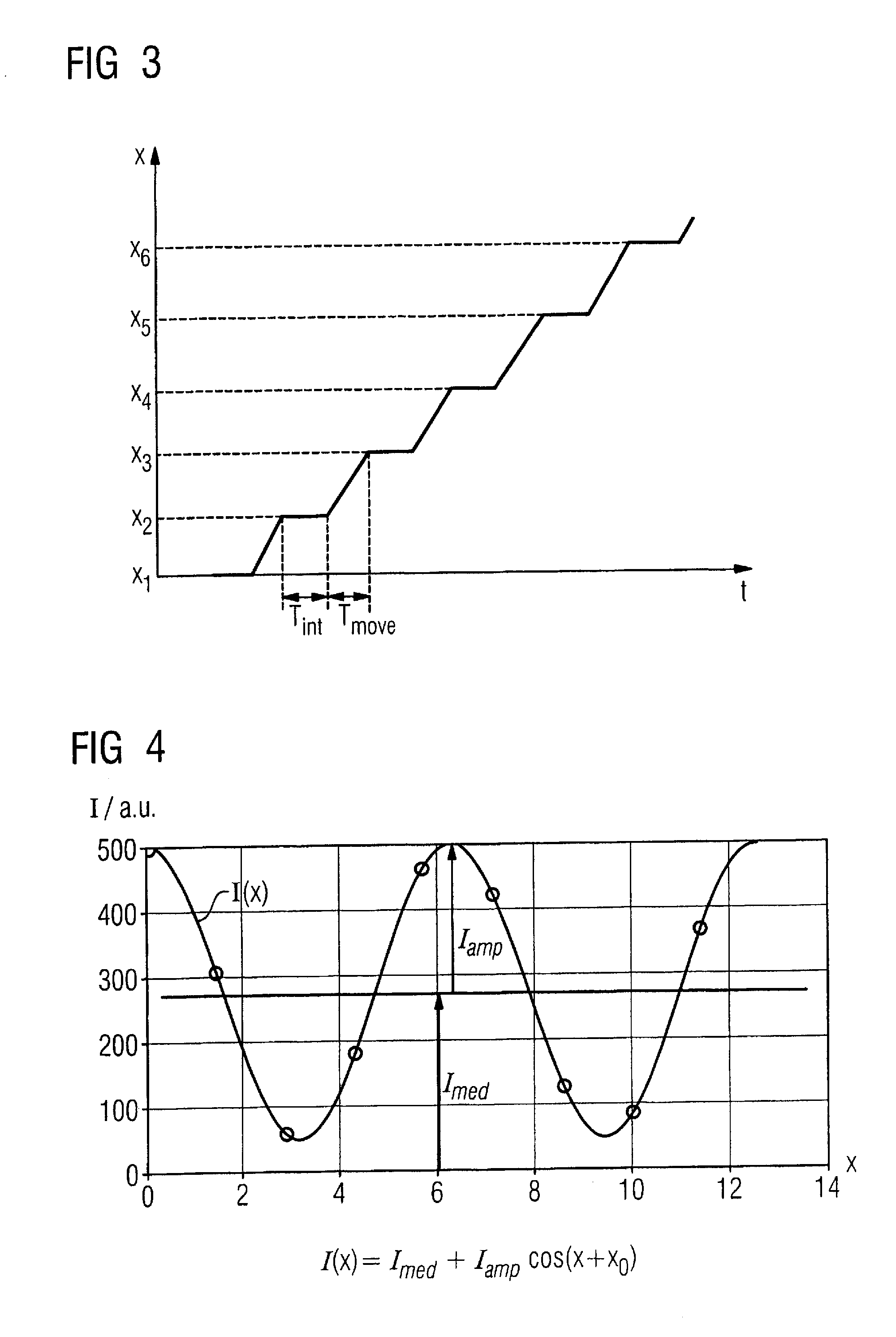
[0041]In the following the invention is described in detail using the preferred exemplary embodiments with the aid of Figures, wherein only the features necessary for understanding the invention are shown. The following reference characters and variables are hereby used: Iamp: sought amplitude portion of the differential intensity values; Imed: sought median value of the intensity; Isweep(t, Δt), Isweep(xi, Δx): integrated intensity measurement value around the point in time ti or the position xi with the measurement interval Δt or, respectively, Δx; Δx, Δt: measurement interval with regard to the grating movement or, respectively, with regard to the measurement time; D: detector; Ei: detector elements; F: focus of a radiation source; G0: source grating; G1: phase grating; G2: analysis grating; I(x): differential intensity curve; O: examination subject; S1, S2: x-ray beams; t: time; Tint: time interval of the integration for measurement; Tmove: time interval of the positioning of th...


PUM

PropertyMeasurementUnit
time periodaaaaaaaaaa
time periodsaaaaaaaaaa
speedaaaaaaaaaa

Abstract

In a method to determine phase and/or amplitude between interfering, adjacent x-ray beams in a detector pixel in a Talbot interferometer for projective and tomographical x-ray phase contrast imaging and/or x-ray dark field imaging, after an irradiation of the examination subject with at least two coherent or quasi-coherent x-rays, an interference of the at least two coherent or quasi-coherent x-rays with the aid of an irradiated phase grating is generated, and the variation of multiple intensity measurements in temporal succession after an analysis grating is determined in relation to known displacements of one of the gratings or of an x-ray source fashioned like a grating, positioned upstream in the beam path, relative to one of the gratings. The integrating intensity measurements ensue during a relative movement—thus not during the standstill—of one of the upstream gratings or of the x-ray source fashioned like a grating or of the examination subject, with known speed behavior over a final time interval of a final distance.

Description

BACKGROUND OF THE INVENTION[0001]1. Field of the Invention[0002]The invention concerns a method to determine phase and / or amplitude between interfering, adjacent x-ray beams in a detector pixel in a Talbot interferometer for projective and tomographical x-ray phase contrast and / or x-ray dark field imaging.[0003]2. Description of the Prior Art[0004]It is known to determine phase and / or amplitude between interfering adjacent x-ray beams in a detector pixel in a Talbot interferometer for projective and tomographical x-ray phase contrast and / or x-ray dark field imaging by producing, after an irradiation of the examination subject with at least two coherent or quasi-coherent x-ray beams—an interference of the two coherent or quasi-coherent x-ray beams using an exposed phase grating, and the variation of multiple intensity measurements in temporal succession after an analysis grating is determined in relation to known relative shifts of a grating positioned in the beam path or of an x-ray...

Claims


Application Information

Patent Timeline
Patent Type & Authority Applications(United States)
IPC IPC(8): H05G1/60G21K1/00G01N23/083
CPCA61B6/06A61B6/4291G21K2207/005A61B6/484
Inventor POPESCU, STEFAN
Owner SIEMENS HEALTHCARE GMBH
Why Eureka
Try Eureka