Diaphragm damper, and method and device for producing the same

Inactive Publication Date: 2006-12-07
EAGLE INDS
View PDF5 Cites 10 Cited by
  • Summary
  • Abstract
  • Description
  • Claims
  • Application Information

AI Technical Summary

Benefits of technology

[0036] According to the production apparatus according to the present invention, it becomes easily to realize the method of production of

Problems solved by technology

However, the high pressure accumulator described in this publication has a large number of parts and is complicated in structure as well.
In production, the step of assembling and welding together the case, plate, and diaphragm and the step of charging the high pressure gas are different, so the number of steps and the number of welded parts are large and the production efficiency is poor.
However, in the method of sealing a sealed relay shown in this publication, since the metal base is placed on the flange of the metal case, the contact parts of the flange and metal

Method used


Image

  • Diaphragm damper, and method and device for producing the same
  • Diaphragm damper, and method and device for producing the same
  • Diaphragm damper, and method and device for producing the same

Examples


Embodiment Construction

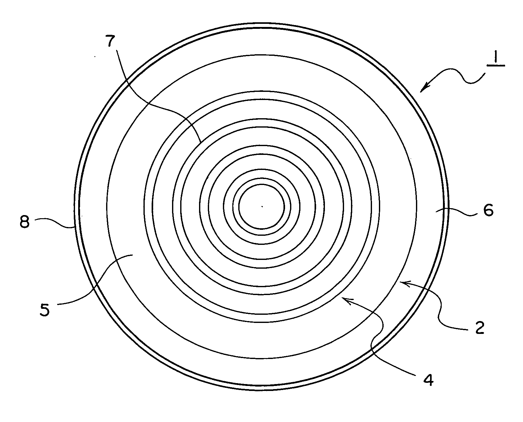
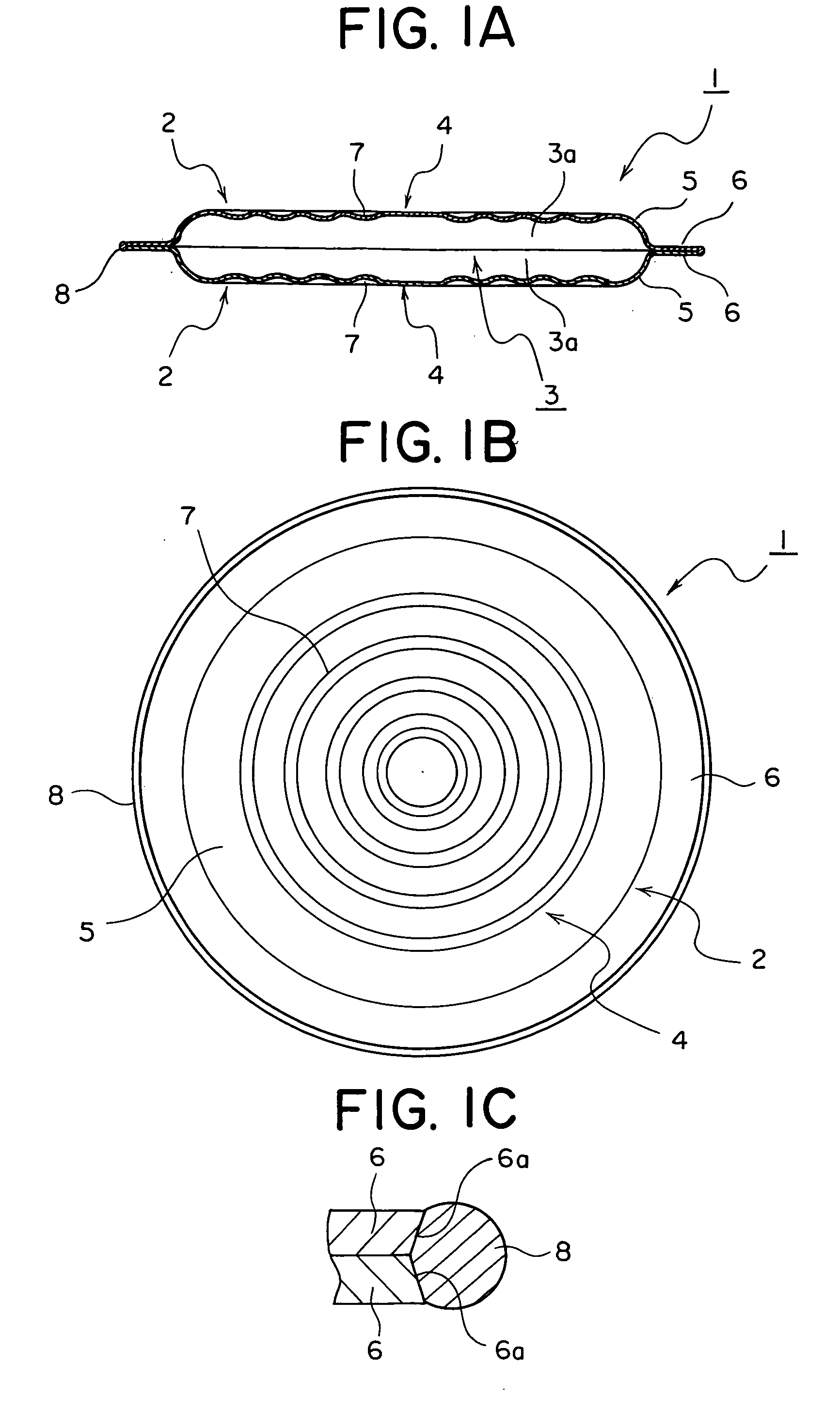
[0043] Below, the present invention will be explained based on an embodiment shown in the drawings. As shown in FIG. 1A, the diaphragm damper 1 according to this embodiment has a pair of diaphragms 2, 2. These diaphragms 2 are formed into the same shapes by thin, flexible metal sheets and, as shown in FIG. 1B, when seen from a plan view, have thin disk shaped flexible parts 4 formed with repeated patterns 7 of coaxial concentric ring-shaped recesses and ring-shaped ridges.

[0044] The outer periphery of each flexible part 4, as shown in FIG. 1A, is integrally formed with a positioning part 5 bent into an arc-shaped cross-section so as to form a half space 3a of the high pressure chamber in combination with the flexible part 4. Further, the outer periphery of this positioning part 5 is integrally formed with a flat ring-shaped flange 6 so as to stick out in the radial direction.

[0045] The flanges 6, 6 of the pair of diaphragms 2, 2 are made to abut against each other and the half spa...


PUM

PropertyMeasurementUnit
Pressureaaaaaaaaaa
Pressureaaaaaaaaaa
Flexibilityaaaaaaaaaa

Abstract

A method of producing a diaphragm damper 1 having a high pressure chamber 3 comprised of two diaphragms 2 with flanges 6 welded together and charged inside with a high pressure gas. The diaphragms 2 are made of magnetically attractable thin metal sheets. A pair of jigs 30, 40 provided to face each other inside the pressure vessel 20 hold the diaphragms 2 by magnetic force. The pressure vessel 20 is sealed and evacuated, then the pressure vessel 20 is charged and pressurized by a mixed gas including helium. After this, the pair of jigs 30, 40 are made to approach each other to make the flanges 6 of the pair of diaphragms 2 come into close contact. Inside the pressure vessel 20, the jigs 30, 40 are simultaneously rotated to rotate the pair of diaphragms 2 and a laser beam is fired at the flanges 6 of the diaphragms 2 to weld the flanges 6 over their entire circumferences.

Description

TECHNICAL FIELD [0001] The present invention relates to a diaphragm damper for absorbing pulsation used in for example a high pressure fuel pump or other location where pulsation occurs and to a method of production and production apparatus for the same. BACKGROUND ART [0002] As a conventional device for absorbing pulsation of this type, the device shown in for example Japanese Patent Publication (A) No. 11-280904 is known. In the device shown in this publication, a fuel pump is equipped with a high pressure accumulator. This high pressure accumulator absorbs part of the pulsation of the pressure of the fuel discharged from the fuel pump to reduce the pulsation width of the fuel pressure and thereby stabilize the amount of injection of fuel. [0003] The high pressure accumulator shown in this publication is provided with a thick disk shaped high pressure vessel constituting a case, a thin metal disk shaped diaphragm sealed and supported by the case at its peripheral edges and working...

Claims


Application Information

Patent Timeline
IPC IPC(8): B21D39/02B23K37/04F16J3/02
CPCB23K26/0823B23K26/12B23K26/123B23K26/125B23K26/206B23K26/28Y10T29/49414F16J3/02B23K26/127Y10T29/49405Y10T29/49893Y10T29/49425B23K37/0443
Inventor MATSUKI, TAKUJISHIMADA, MASAHIDE
Owner EAGLE INDS
Why Eureka
Try Eureka