
Interaction method and communication device

Active Publication Date: 2016-12-29
BEIJING ZHIGU RUI TUO TECH
View PDF6 Cites 1 Cited by
  • Summary
  • Abstract
  • Description
  • Claims
  • Application Information

AI Technical Summary

Benefits of technology

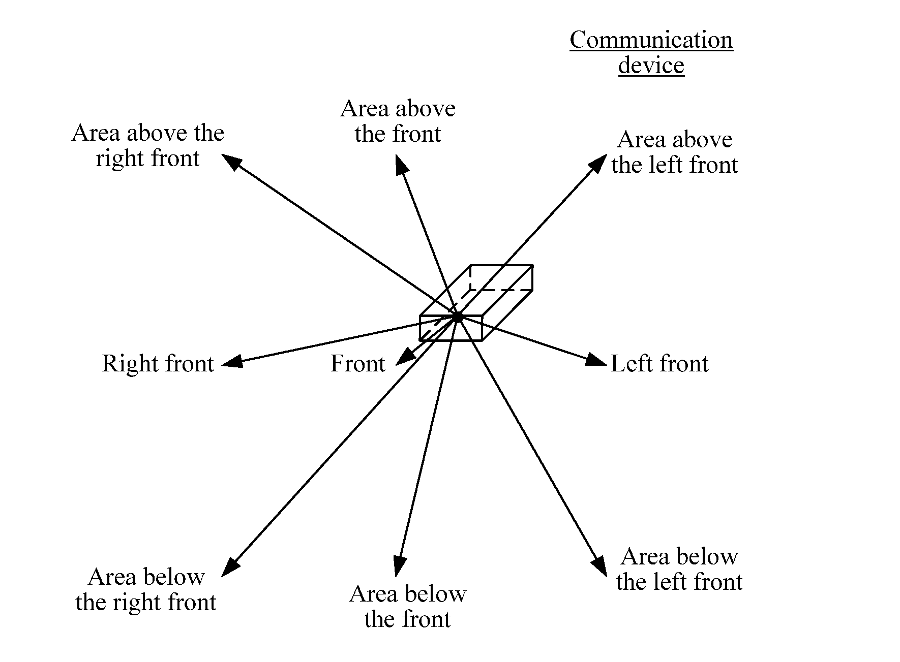
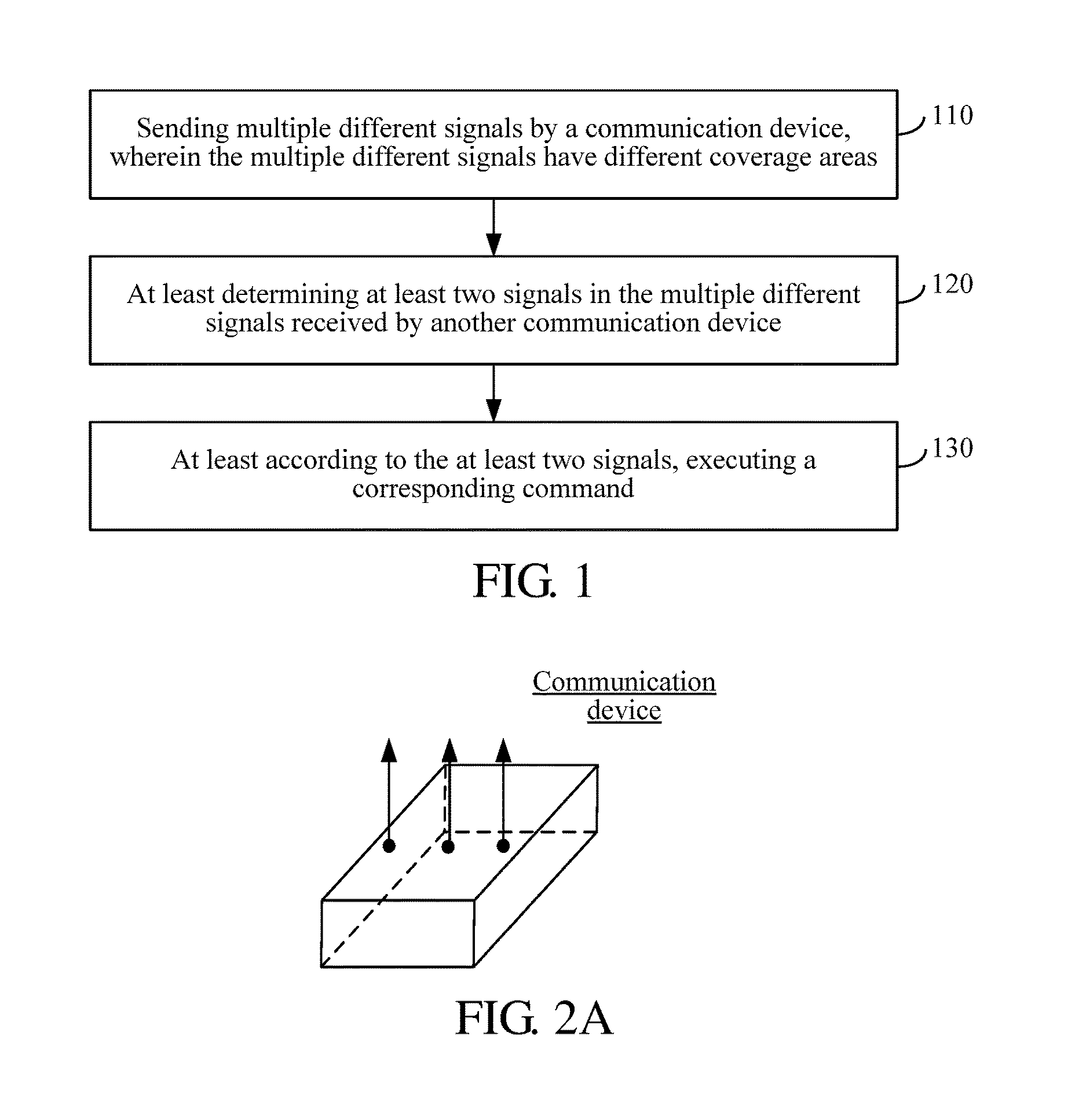
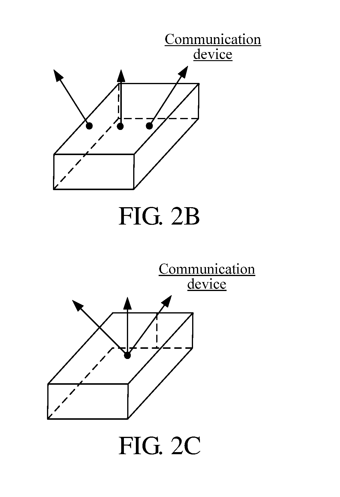
The present application describes a solution for controlling communication between devices by sending different signals with different coverage areas. The other device receives the signals and determines which ones to use. Based on those signals, the first device can execute a corresponding command. The technical benefit is that the interaction between devices is flexible and easy to realize.

Problems solved by technology

One vision-based interaction manner is that one device collects an image of a user or another device by a depth sensor to interact with the user or another device, and such interaction manner has high requirements on calculating complexity and hardware complexity of image collecting.
In addition, use of wireless signals for interaction gains more and more attention of people, for example, a user action is recognized by detecting reflection echo features of a directionally sent wireless signal wave beam, thereby realizing the interaction with the user, but transmission distance of reflected signal is limited generally, and recognition precision is related to the distance, so that application thereof is limited.

Method used


Image

  • Interaction method and communication device
  • Interaction method and communication device
  • Interaction method and communication device

Examples


first embodiment

[0134]FIG. 4 is a structural schematic diagram of a communication device provided by the present application. As shown in FIG. 4, the communication device comprises:

[0135]a sending module 41, configured to send multiple different signals, wherein the multiple different signals have different coverage areas;

[0136]a first determining module 42, configured to at least determine at least two signals in the multiple different signals received by another communication device; and

[0137]an executing module 43, configured to, at least according to the at least two signals, execute a corresponding command.

[0138]In the present embodiment, the communication device 400 can be any device with a communication function, which comprises but not limited to a cellphone, a tablet computer, a smart television, a wearable device and a display.

[0139]In the present embodiment, the word “different” in the phase “multiple different signals” means that the multiple different signals carry different informatio...

second embodiment

[0200]FIG. 6 is a structural schematic diagram of a communication device provided by the present application. As shown in FIG. 6, the communication device 600 comprises:

[0201]at least one signal emitting source 61:

[0202]a memory 62, configured to store at least one program; and

[0203]a processor 63, configured to execute the at least one program stored by the memory 62, wherein the at least one program enables the processor 63 to execute following operations:

[0204]controlling the at least one signal emitting source 61 to send multiple different signals, wherein the multiple different signals have different coverage areas;

[0205]at least determining at least two signals in the multiple different signals received by another communication device; and

[0206]at least according to the at least two signals, executing a corresponding command.

[0207]In the present embodiment, the communication device 600 can be any device with a communication function, which comprises but not limited to a cellph...


PUM


Abstract

An interaction method and communication device are provided. An interaction method comprises: sending multiple different signals by a communication device, wherein the signals have different coverage areas, at least determining at least two signals in the multiple different signals received by another communication device, and at least according to the at least two signals, executing a corresponding command. An interaction solution is thereby provided.

Description

RELATED APPLICATION[0001]The present application claims the benefit of priority to Chinese Patent Application No. 201510358060.5, filed on Jun. 25, 2015, and entitled “Interaction Method and Communication Device”, which application is hereby incorporated into the present application by reference herein in its entirety.TECHNICAL FIELD[0002]Embodiments of the present application relate to the technical field of interaction, and, for example, to an interaction method and a communication device.BACKGROUND[0003]Interaction between men and devices and interaction between the devices can be implemented in many manners. One vision-based interaction manner is that one device collects an image of a user or another device by a depth sensor to interact with the user or another device, and such interaction manner has high requirements on calculating complexity and hardware complexity of image collecting. In addition, use of wireless signals for interaction gains more and more attention of people...

Claims


Application Information

Patent Timeline
IPC IPC(8): H04B7/02H04B7/06
CPCH04B7/028H04B7/0697H04B7/0617
Inventor XU, RANDING, DAYONG
Owner BEIJING ZHIGU RUI TUO TECH
Learn More